


XR2500F Installation Guide Digital Monitoring Products
47
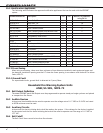
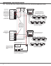
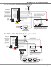
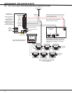
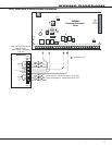
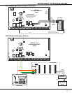
WIRInG dIaGRaMs
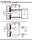
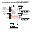
39.10 Second LX-Bus™ with Auxiliary Power Supply
AC
12345678 10 11 12 13 14 15 16 17 18 199202122232425262728
+B BELL GND SMK GNDREDYEL GRNBLK Z1 Z2 Z3 Z4 Z5 Z6 Z7 Z8 Z9+Z9- Z10+ Z10-AC -B GND GND GNDGND
K6 K7
Output 1
Output 2
J3
Phone Line
J10
J22
LX-Bus
Battery
Start
J23
J21
RS-232
Power LED
J8
PROG
J4
Tamper
Out2
J11
3
4
5
6
J2
J1
Ethernet
XR2500F
Command
Processor™ Panel
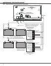
AB C
D
R
L
X
Red
Yellow
Green
Black
S
Red
Yellow
Green
Black
SSSSSS
Red
Yellow
Green
Black
S
Red
Yellow
Green
Black
Red
Yellow
Green
Black
SS
DMP
505-12
716
N/O C N/C
SSSSS
710
100 zones on LX-Bus 1, Numbered 500 to 599.
100 zones on LX-Bus 2, Numbered 600 to 699.
LX-Bus Expansion Cards:
DMP Models 481, 462N, 462P,
463G, and 472 Interface Cards
Do not connect
the red wire
between the
Interface Card
and the first
device.
Connect the red wire to Smoke
Output (terminal 11).
S
= 521LX or 5212LXT
Addressable Smoke Detector
Refer to LT-0310 for more
information about the 710/710F
Bus Splitter/Repeater Module.
LX-Bus 1
LX-Bus 2
Program the 716 Output
Expander Module as
Sensor Reset Output.
J16
Reset
E
481