


XR2500F Installation Guide Digital Monitoring Products
13
InstallatIon
Accessory Devices
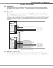
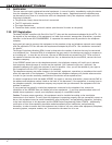
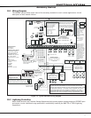
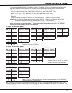
10.1 Wiring Diagram
TheXR2500Fsystembelowshowssomeoftheaccessorymodulesforuseinvariousapplications.Abrief
descriptionofeachmodulefollows.
Heat detectors, pull
stations, or any other
contact devices listed
for Fire Protective
Signaling can be
connected to zones
9 and 10.
Zones 9 and 10 and
Model 715 compatibility
identifier: A
Maximum operating
range: 9.8 VDC to
14.0 VDC.
Class B (Style A).
DMP Transformer
16 VAC 56 VA
Class 2 Wire-in.
Secondary Power Supply
1.0 Amps Max. charging
current. Use only 12 VDC
rechargeable batteries.
DMP Models 365, 366, 367,
368, or 369. Replace
batteries every 3 to 5 years.
Bell
12 VDC nominal
Minimum cutoff time is
5 minutes.
.7 Amp Max
Keypads
Model 630F
60mA at 8 to 14.5 VDC
Auxiliary Power
Total current combined from
terminals 7, 11, 25, and 27
1.9 Amp Max
Listed Resistors
1.0k Ohm - DMP Model 311
3.3k Ohm - DMP Model 309
10K Ohm - DMP Model 308
Bell cutoff time
range is 5 to 99
minutes marchtime
and non-coded.
AC
12345678 10 11 12 13 14 15 16 17 18 199202122232425262728
+B BELLGNDSMK GNDREDYEL GRNBLK Z1 Z2 Z3 Z4 Z5 Z6 Z7 Z8 Z9+ Z9–Z10+Z10–AC –B GNDGND GNDGND
K6 K7
Output 1Output 2
J3
Phone Line
J10
J22
LX-Bus
Battery
Start
J23
J21
RS-232
Power
LED
J8
PROG
J4
Tamper
J16
Reset
Out1 Out2
Outputs 3-6
J11
3
4
5
6
J2
J1
Ethernet
R
L
X
Link LED
Power LED
OVC
XR2500F
Command Processor™
Panel
J6
3.3k Ohm 3.3k Ohm 3.3k Ohm 3.3k Ohm
1k Ohm
Form C Relays (J2)
Output Color Code–Model 431 Harness
Output 2 N/O Orange/White
Output 2 Com White/Gray
Output 2 N/C Violet/White
Output 1 N/O Orange
Output 1 Com Gray
Output 1 N/C Violet
Annunciator Outputs (J11)
Output Color Code
Output 3 Red
Output 4 Yellow
Output 5 Green
Output 6 Black
Front
Tamper
Rear
Tamper
s
RED
BLACK
GROUND
Cold Water
Pipe Earth
Ground
Bell
Zone 1
Zone 2
Zone 3
Zone 4
Zone 5
Zone 6
Zone 7
Zone 8
3.3k
Ohm
Resistor
3.3k
Ohm
Resistor
Zone Expander
Model 715
7mA @ 12 VDC
Models 715-8, 715-16
20mA @ 12 VDC
Smoke
Detector
Use UL Listed Power
Supervision Relay
rated at 12 VDC.
1k Ohm
s
= Supervised Circuit
Zone
9
Zone
10
22 gauge minimum
22 gauge minimum
22 gauge minimum
22 gauge minimum
RED
YELLOW
GREEN
BLACK
1k Ohm 1k Ohm 1k Ohm
Zone Expander
Model 714
7mA @ 12 VDC
Models 714-8, 714-16
20mA @ 12 VDC
RED
YELLOW
GREEN
BLACK
RED
s
s
s
s s s s s
s
s
S S S S S S S S
S S S S
1k
Ohm
SS
1k
Ohm
SS
1k
Ohm
SS
1k
Ohm
SS
1k
Ohm
SS
1k
Ohm
SS
1k
Ohm
SS
1k
Ohm
SS
S SS SS SS S
Zone
Expander
Model 711
7mA @ 12
VDC
10k
Ohm
s
s
s
s
s
Keyswitch Arming
can be connected
to any zone. See
LT-0681.
POWER
TROUBLE
ALARM
COMMAND
1234
5678
90
ABC DEF GHIJKL
MNOPQR STUVWX
YX
ENABLE
SILENCE
RESET
TEST
DRILL
Fire Command Center
Verification
Zones
______
Control Unit
Delay
13.6 sec.
Smoke
Model
______
Detector
Delay
____sec.
Zones 9, 10, and all
expanded zones are
suitable for Class B (as
applicable for the
initiating and signaling
line circuits per ANSI/UL
864 Table 48.2 or 48.3).
Installation limits under
local Authority Having
Jurisdiction (AHJ).
Using verification delays
on zones 9 and 10 is
optional. Use the
delays marked on the
smoke detectors or
the smoke detector
installation wiring
diagram.
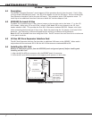
481 Zone Expansion Interface Card
WARNING
THIS UNIT MAY BE PROGRAMMED TO USE AN ALARM VERIFICATION
FEATURE THAT RESULTS IN DELAY OF THE SYSTEM ALARM SIGNAL FROM
THE INDICATED CIRCUITS. THE TOTAL DELAY (CONTROL UNIT PLUS
SMOKE DETECTORS) SHALL NOT EXCEED 60 SECONDS. NO OTHER
SMOKE DETECTOR SHALL BE CONNECTED TO THESE CIRCUITS UNLESS
APPROVED BY THE LOCAL AUTHORITY HAVING JURISDICTION (AHJ).
WARNING: Incorrect
connections may cause
damage to the unit.
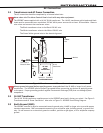
CAUTION: DO NOT USE LOOPED WIRE
UNDER TERMINALS. BREAK WIRE RUN TO
PROVIDE SUPERVISION OF CONNECTIONS.
¼"
AC Wiring must be in conduit and exit
out the left side of the enclosure.
Wiring on terminals 5 through 22 must
exit right and maintain 1/4" separation
from the AC and battery positive wiring.
Figure 12: Typical XR2500F Wiring Diagram
10.2 Lightning Protection
MetalOxideVaristorsandTransientVoltageSuppressorshelpprotectagainstvoltagesurgesonXR2500Finput
andoutputcircuits.AdditionalsurgeprotectionisavailablebyinstallingtheDMP370or370RJLightning
Suppressors.