


XR2500F Installation Guide Digital Monitoring Products
i
taBle oF Contents
Introduction
1.1 Overview ...................................................................................................... 1
1.2 System Components ...................................................................................... 1
1.3 Power Specications ...................................................................................... 1
1.4 Communication ............................................................................................. 1
1.5 Panel Zones .................................................................................................. 1
1.6 Keypad Bus ................................................................................................... 1
1.7 LX-Bus™ ....................................................................................................... 2
1.8 Outputs ........................................................................................................ 2
1.9 Relays .......................................................................................................... 2
1.10 Zone Reference ............................................................................................. 2
1.11 Compliance Instructions ................................................................................. 2
Mounting
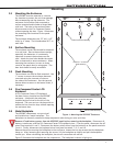
2.1 Mounting the Enclosure .................................................................................. 3
2.2 Surface Mounting .......................................................................................... 3
2.3 Flush Mounting .............................................................................................. 3
2.4 Fire Command Center LCD Keyboard ............................................................... 3
2.5 Metal Backplate ............................................................................................. 3
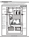
2.6 Wiring Diagram ............................................................................................. 4
AC Connection
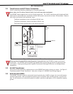
3.1 Transformers and AC Power Connection .......................................................... 5
3.2 16 VAC Transformer ...................................................................................... 5
3.3 Earth Ground (GND) ..................................................................................... 5
Secondary Power Supply
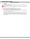
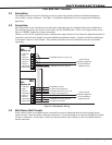
4.1 Description .................................................................................................... 6
4.2 Battery Connection to XR2500F Command Processor panel ............................... 6
Two 866 NAC Modules
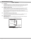
5.1 Description .................................................................................................... 7
5.2 Connection .................................................................................................... 7
5.3 Bell Silence/Bell Trouble ................................................................................. 7
LX-Bus™ Operation
6.1 Description .................................................................................................... 8
6.2 XR2500F On-board LX-Bus ............................................................................ 8
6.3 LX-Bus 481 Zone Expansion Interface Card ...................................................... 8
6.4 Installing the 481 Card ................................................................................... 8
893A Dual Phone Line Module
7.1 Description .................................................................................................... 9
7.2 Connection .................................................................................................... 9
7.3 Jumper Settings ............................................................................................ 9
7.4 Digital Dialer ................................................................................................. 9
7.5 Phone Line Monitor ........................................................................................ 9
7.6 Processor Fail Buzzer ..................................................................................... 9
7.7 J10 893A Connector ....................................................................................... 9
7.8 Ground start .................................................................................................. 9
7.9 Notication ..................................................................................................10
7.10 FCC Registration ..........................................................................................10
Fire Command Center
8.1 Description ...................................................................................................11
8.2 Connection ...................................................................................................11
8.3 Remote Fire Command Center .......................................................................11
Expansion
9.1 Zone Expansion ............................................................................................12
9.2 Output Expansion .........................................................................................12