


Digital Monitoring Products XR2500F Installation Guide
20
InstallatIon
Bell Output
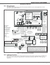
12.1 Terminals 5 and 6
Terminal5suppliespositive12VDCregulatedpowerforalarmbellsorhorns.Thisoutputcanbesteady,
pulsed,ortemporaldependingupontheBellActionspeciedinOutputOptions.Terminal6istheground
referenceforthebellcircuit.Thissupervisedoutputdetects10kOhmsorlessasnormal.Theindicating
appliancecansupplythisresistance.Ifusingahornorsiren,a1kOhm1/2WEOLresistor(provided)should
beaddedacrossthebellcircuittoprovidesupervision.SeetheNoticationAppliancesectionforalistof
approvednoticationappliancesandtheWiringDiagramsforconnections.
Keypad Bus
13.1 Description
XR2500Fpanelterminals7,8,9,and10areforthekeypadbus.InadditiontoFireCommandCentersand
RemoteFireCommandCenters,youcanconnectuptofteensupervisedkeypadsandmultipleunsupervised
keypadstotheXR2500F.InadditiontoSecurityCommandkeypads,youcanalsoconnectanycombination
ofzoneexpansionmodules,5845LXGlassbreakdetectors,and6155LXPIRstothedatabus.Refertothe
specicdeviceInstallationsheetforthemaximumnumberofkeypadBusdevices.
RefertothesectiontitledLX-BusforcompleteinformationabouttheLX-Bus4-pinheaderandexpansion
slot.
Note:DonotuseshieldedwireforLX-Bus/KeypadBuscircuits.
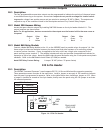
13.2 Terminal 7 - RED
Thisterminalsuppliespositive12VDCregulatedtopowerFireCommandCentersandzoneexpansion
modules.Terminal7alsosuppliespowerforanyauxiliarydevice.Thegroundreferenceforterminal7is
terminal 10.
Theoutputcurrentissharedwiththesmokepoweroutputonterminal11andZones9and10.Currentdraw
forallconnecteddevicesmustnotexceedthepanelmaximumcurrentrating.SeePowerSupplyinthe
Compliancesectionformaximumcurrentinarelistedapplication.
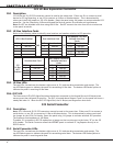
13.3 Terminal 8 - YELLOW
Terminal8receivesdatafromkeypadsandzoneexpansionmodules.Itcannotbeusedforanyother
purpose.
13.4 Terminal 9 - GREEN
Terminal9transmitsdatatokeypadsandzoneexpansionmodules.Itcannotbeusedforanyotherpurpose.
13.5 Terminal 10 - BLACK
Terminal10isthegroundreferenceforFireCommandCenters,zoneexpansionmodules,andallauxiliary
devicesbeingpoweredbyterminal7.
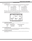
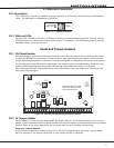
13.6 J8 Programming Connection
A4-pinheader(J8)isprovidedtoconnectakeypadwhenusingaDMPModel330ProgrammingCable.This
providesaquickandeasyconnectionforpanelprogramming.
YoumayalsousetheJ8ProgrammingHeadertoconnectKeypadBusdevices.Thisisanalternativeto
connectingkeypadbusdevicestoterminals7,8,9,and10.
13.7 OVC LED
TheOvercurrentLED(OVC)lightsRedwhenthedevicesconnectedtotheKeypadBusandLX-Bus(es)draw
morecurrentthanthepanelisratedfor.TheOVCislocatedaboveOutputs1and2onthepanelandturnsa
steadyRedwhenlit.WhentheOVCLEDlightsRed,theLX-Bus(es)andKeypadbusareshutdown.