


XR2500F Installation Guide Digital Monitoring Products
15
InstallatIon
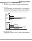
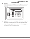
10.4 Mounting Keypads and Zone Expansion Modules
LCDkeypadshaveremovablecoversthatallowmountingthekeypadtoawallorotheratsurfaceusingthe
screwholesoneachcornerofthebase.Beforemountingthebase,connectthekeypadwireharnessleads
tothekeypadcablefromthepanelandtoanydevicewiringruntothatlocation.Thenattachtheharnessto
thepinconnectoronthePCboard,mountthebase,andinstallthekeypadcovermakingsureallofthekeys
extendthroughtheirrespectiveholes.
Formountingkeypadsonsolidwalls,orforapplicationswhereconduitisrequired,usetheModel6951-1/2”
deeportheModel6961/2”deepbackboxes.
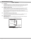
TheDMP711,714,715,716,and717modulesareeachcontainedinmoldedplastichousingswithremovable
covers.Thebaseprovidesyouwithmountingholesforinstallingtheunittoawall,switchplate,orother
surface.
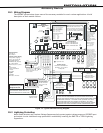
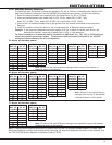
10.5 Connecting LX-Bus and Keypad Bus Devices
SeveralfactorsdeterminetheDMPLX-Bus™andkeypadbusperformancecharacteristics:thewirelengthand
gaugeused,thenumberofdevicesconnected,andthevoltageateachdevice.WhenplanninganLX-Bus™
andkeypadbusinstallation,keepinmindthefollowinginformation:
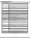
1.DMPrecommendsusing18or22-gaugeunshielded wireforallkeypadandLX-Buscircuits.Do not use
twistedpairorshieldedwireforLX-Busandkeypadbusdatacircuits.
2.Onkeypadbuscircuits,tomaintainauxiliarypowerintegritywhenusing22-gaugewiredonotexceed500
feet.Whenusing18-gaugewiredonotexceed1,000feet.Toincreasethewirelengthortoadddevices,
installanadditionalpowersupplythatislistedforFireProtectiveSignaling,powerlimited,andregulated
(12 VDC nominal) with battery backup.
Note:Eachpanelallowsaspecicnumberofsupervisedkeypads.Addadditionalkeypadsinthe
unsupervisedmode.Refertothepanelinstallationguideforthespecicnumberofsupervisedkeypads
allowed.
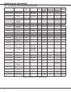
3.Maximumdistanceforanyonebuscircuit(lengthofwire)is2,500feetregardlessofthewiregauge.This
distancecanbeintheformofonelongwirerunormultiplebrancheswithallwiringtotalingnomore
than2,500feet.Aswiredistancefromthepanelincreases,DCvoltageonthewiredecreases.Maximum
numberofLX-Busdevicesontherst2,500footcircuitis40devices.
4.Maximumvoltagedropbetweenthepanel(orauxiliarypowersupply)andanydeviceis2.0VDC.Ifthe
voltageatanydeviceislessthantherequiredlevel,addanauxiliarypowersupplyattheendofthe
circuit.Whenvoltageistoolow,thedevicescannotoperateproperly.
ForadditionalinformationrefertotheLX-Bus/KeypadBusWiringApplicationNote(LT-2031).
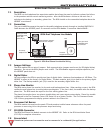
Expansion Interface Cards (Models 481, 462N, 462P, 463G, and 472)
TheLX-Busprovidedonthesecardsrequiresonlya4-wirecablebetweenthecardandanydevices
connectedtothebus.Youcanconnectdevices(zoneoroutputexpansionmodules)togetheronthesame
cableorprovideseparaterunsbacktothecard.EachLX-Busprovidesupto100zonesoroutputs.
Note:DonotusetwistedpairorshieldedwirewhenconnectinganLX-Busorkeypadbus.