


Digital Monitoring Products XR2500F Installation Guide
44
WIRInG dIaGRaMs
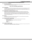
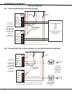
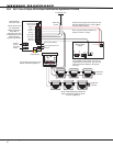
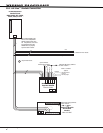
39.7 867 Class B Style W Multiple Notication Appliance Circuits
Model 310
1K EOL
To initiating zone
Normal/Silence Switch
Ground Fault LED
Bell Trouble LED
Bell In + 1
Bell In - 2
Bell Out + 3
Bell Out - 4
Bell Trouble 5
Bell Trouble 6
PWR Mon. 7
Mon. RTN 8
TENSONES
TENSONES
Bell Relay
Address
Supervisory
Address
Bell Ring Style (Steady)
Power Supply Monitor LED
Data LED
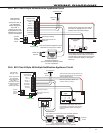
505-12 Power
Supply
J6
+ DC -
AC
Trouble
Batt
Trouble
J4
J3J2
Green
LED
AC
AC
+ BAT -
Red
LED
DC
12 VDC @ 5 Amps
Battery
Start
The Auxiliary Power Supply and Notification
Circuit Module trouble contact zone must be
programmed as a Supervisory Type zone and
must be selected for display in the keypad
status list.
Auxiliary Power Supply must be Listed for Fire
Protective Signaling Service. Power Supplies
must have battery backup.
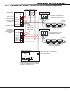
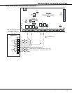
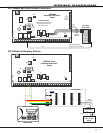
LX-Bus Wiring
DMP Model 867
30mA @ 12 VDC
The 867 must have its
own independent
address ranging from
500 to 999. A
Supervisory zone must
be programmed into the
panel to properly
supervise each module.
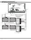
MINUS 2MINUS 1+OUT 1 +IN 1 +IN 2-AUD+AUD +OUT 2
Model 308
10K EOL
Listed, Polarized Notification Appliances
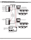
DSM-12/24 Module
Model 308
10K EOL
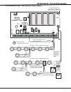
See the Notification Appliance section
for a list of appliances.
When using an DSM Sync Module, the
maximum current is 3 Amps.
Sync module required when using
multiple notification appliances