


XR2500F Installation Guide Digital Monitoring Products
5
IntRoduCtIon
AC Connection
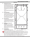
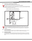
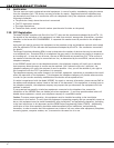
3.1 Transformers and AC Power Connection
The AC connection should be completed by a licensed electrician.
Never share the Fire Alarm Control Panel circuit with any other equipment.
TheXR2500Fcomessuppliedwitha16VAC56VAtransformer.The16VACtransformerwhiteleadsandblack
leadsmustbeconnectedtoanunswitched120VAC60Hzpowersourcewithatleast.87Aavailable.Observe
wirecolorsandconnectthetransformerwires:
TheBlacktransformerwirestotheBlack120VACwire
TheWhitetransformerwirestotheWhite120VACwire
TheGreen/Yellowgroundwiretotheelectricalground
S
56 VA
Transformer
To XR2500F Panel
Violet
Terminal 1
Gray
Terminal 2
16 VAC
56 VA
Transformer
L-Bracket
Bracket
Nut
Bracket
Nut
GROUND
GREEN
GREEN/
YELLOW
WHITE
BLACK
WHITE
BLACK
S
S
Connected to
Enclosure Door
Figure 3: Transformers and AC Power Connection
Always ground the panel before applying power to any devices! Use18AWGorlargerforallpower
connections.TheXR2500Fmustbeproperlygroundedbeforeconnectinganydevicesorapplyingpower
tothepanel.PropergroundingprotectsagainstElectrostaticDischarge(ESD)thatcandamagesystem
components.
3.2 16 VAC Transformer
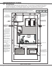
The16VAC56VAtransformersuppliespowertotheXR2500Fpanelandisfactorypre-wired.SeeFigure3:
TransformersandACPowerConnection.AlsorefertoFigure11:XR2500FPanelWiringDiagram.
3.3 Earth Ground (GND)
TheXR2500Fterminal4mustbeconnectedtoearthgroundusing14AWGorlargerwiretoprovideproper
transientsuppression.DMPrecommendsconnectingtoacoldwaterpipe,buildingground,orgroundrod
only.Donotconnecttoanelectricalgroundorconduit,sprinklerorgaspipes,ortoatelephonecompany
ground.