


Digital Monitoring Products XR2500F Installation Guide
4
IntRoduCtIon
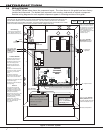
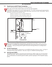
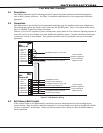
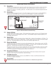
2.6 Wiring Diagram
TheXR2500Fsystembelowshowsthecomponentlayout.Thewiresshowninthisguidehavebeenfactory
installedandconnected.Thedashedlinesrepresentwiresrunningunderneathorbehindacomponent.
Detailedwiringdiagramsforeachsuppliedcomponentappearinfollowingsectionsofthisguide.
AC
12345 678 10 11 12 13 14 15 16 17 18 199202122232425262728
+B BELLGND SMKGNDREDYELGRNBLK Z1 Z2 Z3 Z4 Z5 Z6 Z7 Z8 Z9+Z9–Z10+Z10–AC –B GND GND GNDGND
Output 1Output 2
J3
Phone
Line
J22
Battery
Start
Power
LED
J8
PROG
J4
Tamper
J16
Reset
Out1 Out2
Outputs 3-6
3
4
5
J1
Ethernet
R
L
X
Link LED
Power LED
OVC
XR2500F
Command
Processor™
Panel
J6 Expansion
Card Slot
TYPES OF SERVICE
Suitable for Mercantile Local
and Police Station Connect.
Suitable for Proprietary, PPU,
other technologies, local.
Suitable for Signaling and
Remote Station PPU DACT
Service.
Suitable for manual fire alarm,
automatic fire alarm, sprinkler
supervisory, or water flow
alarm.
Suitable for Standard or
Encrypted Central Station with
NET or CELL communication.
Suitable for Household Fire and
Household Burglary.
Suitable for Coded and March
Time signaling.
NFPA 72
This equipment should be
installed in accordance with
the National Fire Alarm Code,
ANSI/NFPA 72 (National Fire
Protection Association,
Batterymarch Park, Quincy, MA
02269). Printed information
describing proper installation,
operation, testing,
maintenance, evacuation
planning, and repair service is
to be provided with this
equipment.
Zones 9, 10, and all expanded
zones are suitable for Class B
(as applicable for the initiating
and signaling line circuits per
ANSI/UL 864 Table 48.2 or
48.3). Installation limits under
local Authority Having
Jurisdiction (AHJ).
Control Unit
Delay
Smoke
Model
Detector
Delay
Verification
Zones
WARNING
THIS UNIT MAY BE PROGRAMMED TO USE AN ALARM VERIFICATION FEATURE THAT RESULTS IN DELAY OF THE
SYSTEM ALARM SIGNAL FROM THE INDICATED CIRCUITS. THE TOTAL DELAY (CONTROL UNIT PLUS SMOKE
DETECTORS) SHALL NOT EXCEED 60 SECONDS. NO OTHER SMOKE DETECTOR SHALL BE CONNECTED TO THESE
CIRCUITS UNLESS APPROVED BY THE LOCAL AUTHORITY HAVING JURISDICTION (AHJ).
See LT-0759, 893A
Dual Phone Line
Module section
for complete 893A
information.
Refer to LT-0759, Standby
Battery Selection section
for battery standby times and
numbers of batteries to use.
See LT-0759, Two 866
NAC Modules section for
complete 866 information.
866
Module
866
Module
+-+
-
12 VDC battery
Two 12 VDC batteries
connected in parallel with a
Model 318 Dual Battery
Harness. See Secondary
Power Supply section.
XR2500F Secondary Power Supply
1 Amp maximum charge current.
Use only 12 VDC rechargeable batteries.
Replace every 3 to 5 years.
12 VDC battery
Black
Red
To Fire Command Center on enclosure door
From XR2500F
panel to 12 VDC.
56 VA
Transformer
GROUND
GREEN
GREEN/
YELLOW
WHITE
BLACK
WHITE
BLACK
To Telco
S
To Notification
Appliances
S
S
S
S
S
S
S
S
Battery Compartment
10K EOL
10K EOL
16 VAC
Expansion Zones
Connected to
Enclosure Door
Use Marking
Commercial and Residential
Fire, Burglar, Holdup, and
Access Protected Premise Unit
Figure 2: XR2500F System