


Digital Monitoring Products XR2500F Installation Guide
ii
taBle oF Contents
Accessory Devices
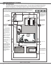
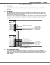
10.1 Wiring Diagram ............................................................................................13
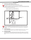
10.2 Lightning Protection ......................................................................................13
10.3 Accessory Devices ........................................................................................14
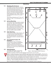
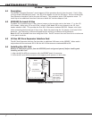
10.4 Mounting Keypads and Zone Expansion Modules .............................................15
10.5 Connecting LX-Bus and Keypad Bus Devices ...................................................15
Battery Information
11.1 Battery Only Restart .....................................................................................16
11.2 Battery Replacement Period...........................................................................16
11.3 Discharge/Recharge ......................................................................................16
11.4 Battery Supervision .......................................................................................16
11.5 Battery Cutoff ...............................................................................................16
12.6 XR2500F Power Requirements .......................................................................16
11.7 XR2500F Standby Battery Calculations ...........................................................17
11.8 Standby Battery Selection .............................................................................19
Bell Output
12.1 Terminals 5 and 6 .........................................................................................20
Keypad Bus
13.1 Description ...................................................................................................20
13.2 Terminal 7 - RED ..........................................................................................20
13.3 Terminal 8 - YELLOW ....................................................................................20
13.4 Terminal 9 - GREEN ......................................................................................20
13.5 Terminal 10 - BLACK .....................................................................................20
13.6 J8 Programming Connection ..........................................................................20
13.7 OVC LED ......................................................................................................20
Smoke and Glassbreak Detector Output
14.1 Terminals 11 and 12 .....................................................................................21
14.2 Current Rating ..............................................................................................21
Powered Zones for 2-Wire Smoke Detectors
15.1 Terminals 25–26 and 27–28 ..........................................................................21
15.2 Compatible 2-Wire Smoke Detector Chart .......................................................22
Protection Zones
16.1 Terminals 13–24 ...........................................................................................23
16.2 Operational Parameters .................................................................................23
16.3 Zone Response Time .....................................................................................23
16.4 Keyswitch Arming Zone .................................................................................23
Dry Contact Relay Outputs
17.1 Description ...................................................................................................24
17.2 Contact Rating .............................................................................................24
17.3 Output Harness Wiring ..................................................................................24
J11 Annunciator Outputs
18.1 Description ...................................................................................................25
18.2 Model 300 Harness Wiring .............................................................................25
18.3 Model 860 Relay Module ...............................................................................25
J23 6-Pin Header
19.1 Description ...................................................................................................25
J22 LX-Bus Expansion Connector
20.1 Description ...................................................................................................26
20.2 LX-Bus Interface Cards ..................................................................................26
20.3 LX-Bus LEDs .................................................................................................26
20.4. OVC LED ........................................................................................................26
J21 Serial Connector
21.1 Description ...................................................................................................26
21.2 Serial Connector LEDs ...................................................................................26