


Crestron CLS-C6RF iLux
™
Integrated Lighting System w/infiNET
™
Hardware Hookup
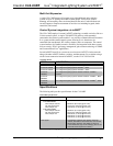
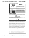
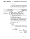
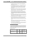
Refer to the following diagram for connection of the AC wiring. Connect each load
wire to the corresponding LOAD terminals on the unit, connect the power line hot
wire from the circuit breaker to the HOT terminal on the unit, connect all neutral
wires to the NEUTRAL terminal on the unit, and connect all ground wires to the
(ground) terminal on the unit. For details, refer to the iLux Lighting System
Installation Guide, Doc. 6416 for CLS-C6RF/C6MRF units, and Doc. 6417, for
CLSI-C6RF/C6MRF units.
Refer to the configuration diagram on the previous page for typical connections to
the LOCAL DEVICES connector.
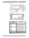
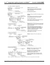
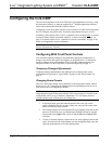
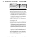
Adding External Power Supplies
Additional power supplies are required to support more than four keypads or shade
controllers on the local devices network. Also, each C2N-SDC-DC shade controller
requires its own additional power supply. The following diagram illustrates a
scenario where an external power supply is required to add keypads and shade
controllers to a network that already contains four shade controllers. The actual
quantity of external power supplies required depends on your system configuration.
Operations Guide - DOC. 6418A iLux
™
Integrated Lighting System w/infiNET
™
: CLS-C6RF • 11