


Crestron CLS-C6RF iLux
™
Integrated Lighting System w/infiNET
™
Connectors, Controls, & Indicators (Continued)
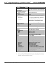
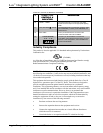
# CONNECTORS,
CONTROLS, &
INDICATORS
DESCRIPTION
5 Motion Detector (CLS/CLSI-
C6MRF only)
The built-in motion detector can be used to activate
a particular scene when there is activity in the room,
and/or to activate a particular scene (typically Off)
when there is no activity for a specified period. A
limited number of actions are available when
programmed locally; more are available using the
iLux Designer software program.
6 Mini Phone Jack Use this 3.5mm TRS mini-phone jack, located on
the front panel, as an RS-232 programming port, to
communicate with the iLux Designer and Crestron
Toolbox
™
to configure the unit, and to upgrade the
unit’s firmware.
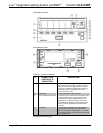
7 Two-Digit Display In Standard mode, the display is normally blank,
except when showing scene fade time. The Min and
Sec LEDs illuminate when the display is indicating
time in minutes or in seconds, respectively. In Setup
mode, the display uses a two-character mnemonic
to indicate which specific aspect of the CLS-C6RF
you are changing. As these are being adjusted, the
display may indicate values. (Refer to “Setup Mode”
on page 13 for details.)
8 Lights Pushbutton and LED Use this switch to select the Lights mode. The LED
illuminates when the mode is selected. Refer to
“Lights Mode” on page 36 for details.
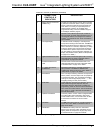
9 Shades Pushbutton and
LED
Use this switch to select the Shades mode. The
LED illuminates when the mode is selected. Refer
to “Shades mode” on page 37 for details.
10
^, v, Save, and Cancel
Pushbuttons
Use these pushbuttons to navigate and execute
setup functions. The Save and Cancel LEDs
indicate when these functions are active. Refer to
“Setup Mode” on page 13 for details.
11 Reset Button If the unit stops functioning and does not respond to
button pushes, use a thin object such as a paperclip
to activate this switch. The unit reboots (all lighting
loads go off, the two-digit display shows “– –,” and
all lighting loads go to their previous state).
12 Shift LEDs These LEDs are covered by the label strip, but are
easily visible through the strip when they are
illuminated. When the Shift mode is enabled via
programming, there can be two functions defined for
each of the six function buttons. The unit will always
be in “upper” or “lower” shift mode as indicated by
the state of the LEDs.
13 Up/Down Pushbutton This three position “rocker” switch is programmable
for master lights control (all lights or last scene),
master shade control, or as a “shift” button to allow
a second set of functions for the six function
buttons.
14 ON Button The ON button always acts as a recall scene button
for the “On” scene. Refer to “Standard mode” on
page 33 for details.
15 OFF Button The OFF button always acts as a recall scene
button for the Off scene, which will always turn all
lighting loads off and open the air-gap relay. Refer
to “Standard mode” on page 33 for details.
(Continued on following page)
Operations Guide - DOC. 6418A iLux
™
Integrated Lighting System w/infiNET
™
: CLS-C6RF • 7