


65
SECTION V - OPERATING INSTRUCTIONS
1. CLEAN HEATING SYSTEM IF boiler water
is dirty. Refer to step (F) for proper cleaning
instructions for water boilers.
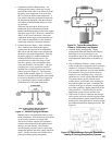
Fill entire Heating System with water and vent air
from system. Use the following procedure on a
Series Loop or Multi-zoned System to remove air
from system when lling:
a.
Close isolation valve in boiler supply piping.
b. Isolate all circuits by closing zone valves or
balancing valves.
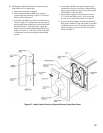
c. Attach a hose to hose bib located just below
isolation valve in boiler supply piping.
(Note - Terminate hose in ve gallon bucket at a
suitable oor drain or outdoor area).
d.
Starting with one circuit, open zone valve.
e. Open hose bib.
f. Open ll valve (Make-up water line should be
located directly above isolation valve in boiler
supply piping.
g. Allow water to overow from bucket until
discharge from hose is bubble free for 30
seconds.
h. Open zone valve to the second zone to be
purged, then close the rst. Repeat this step until
all zones have been purged, but always have one
zone open. At completion, open all zone valves.
i. Close hose bib, continue lling the system until
the pressure gauge registers normal system
design operating pressure. Close ll valve.
(Note
- If make-up water line is equipped
with pressure reducing valve, system will
automatically ll to normal system design
operating pressure. Leave globe valve open).
j. Open isolation valve in boiler supply piping.
k. Remove hose from hose bib.
DANGER
Do not operate boiler with pressure above
maximum allowable working pressure listed on
the Boiler’s ASME Data Label.
DO NOT draw water from boiler while in use.
When adding water while boiler is in operation,
do not open supply valve fully but add water
slowly.
with burner service switch turned
“OFF”.
1. PRESS RESET BUTTON on primary control and
release.
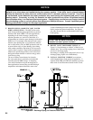
2. BOILER OPERATING AQUASTAT - The
operating aquastat, L4006A should be set to the
designed supply temperature, typically 180°F.
3. BOILER HIGH LIMIT AQUASTAT - The high
limit aquastat, L4006E, can be identied with a red
manual
reset button. Ideally, the high limit aquastat
should be set high enough above the operating
aquastat setting so as to avoid nuisance shutdowns
on manual reset. The temperature must be set below
the maximum permissible temperature for any
system related component affected by boiler supply
water. Under no circumstances can the high limit
aquastat be set higher than 250°F.
according to the Burner Manual.
The MPC boiler controls operate the burner
automatically. If for unknown reasons the burner
ceases to re and the reset button on the primary control
is
tripped, the burner has experienced ignition failure.
Before pressing the reset button, call your serviceman
immediately.
WARNING
Do not attempt to start the burner when excess
oil or gas has accumulated in the combustion
chamber, when the unit is full of vapor, or when
the combustion chamber is very hot.
WARNING
If you do not follow these instructions exactly,
a re or explosion may result causing property
damage or personal injury.
If any unusual or improper operation or site condi-
tions are observed, turn the boiler off and contact
an experienced and skilled service agency.
Follow component manufacturer’s instructions.
Component manufacturer’s instructions were
provided with the boiler. Contact component
manufacturer for replacement if instructions
are missing. Do not install, start up, operate,
maintain or service this boiler without reading and
understanding all of the component instructions.
Do not allow the boiler to operate with altered,
disconnected or jumpered components. Only
use replacement components identical to those
originally supplied with the boiler and burner.