


23
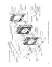
2. ASSEMBLY OF SECTIONS
• MPC4 through MPC12 Section Assemblies
The entire assemblage may be drawn-up at one time
using the hydraulic draw-up equipment providing
the operation is completed within two (2) hours after
the sealant was applied to the rst casting in the
assembly. If time limit is reached, draw-up partial
section assembly before continuing.
• MPC13 through MPC18 Section Assemblies
The total assemblage should be rst drawn-up into
two (2) sub-assemblies. Each sub-assembly may be
drawn-up at one time using the hydraulic draw-up
equipment providing the operation is completed
within two (2) hours after the sealant was applied to
the rst casting in the sub-assembly. No more than
12 sections should be drawn up at one time.
“Hydraulic Draw-Up Tool Kit” is available through
Burnham by ordering part number 101904-01.
Step a. Repeat Step ‘a’ through Step ‘l’ under
“Field Assembled Sections (Manual Draw-Up)”.
Continue driving sections in place (in their
respective order) until all sections are in the
assemblage. Ground surfaces between adjoining
sections should be spaced 3/8” to 1/2” apart.
Spacing of more than 1/2” will limit number of
sections that can be drawn up in one unit and
could indicate cocked nipples.
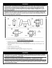
WARNING
Sealant must be properly applied to ALL boiler
joints. Failure to properly seal the boiler joints
will result in combustion gas leaks through the
joint. DO NOT operate boiler with combustion
gas leaks. The sealant should be applied before
each section is placed on the assembly.
On long boiler assemblies, it may be necessary
to draw up a partial block if the entire boiler is not
ready to be drawn up tight within two (2) hours
of the rst application of the Silastic. If the block
assembly
time extends overnight, the partial block
completed must be drawn up tight before leaving
the boiler overnight. If a joint springs apart, it
must be re-drawn tight within two (2) hours of rst
application
of Silastic to the joint.
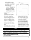
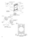
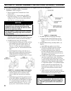
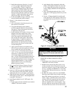
From the Hydraulic Draw-up Kit, locate and
assemble one (1) set of draw-up assemblies that
each include ¾” x 23” lg. threaded rod(s), ¾”
coupling nut(s) (if applicable), the appropriate
pressure plate, washer and ¾” hex nut as shown
in Figure 5. Insert one (1) assembly through
each of the 3” and 4” NPT bosses on rear section
until pressure plate is tight against the boss.
Locate and place the 8¾” dia. pressure plate on
the opposite end of threaded rod in upper nipple
port. Place remaining 6½” dia. pressure plate on
rod protruding through lower nipple port.
NOTICE
As assembled length increases, use 3/4” coupling
nuts and additional rods, provided in Kit, to extend
draw-up rod length.
Slide ¾” washer, hydraulic ram and second ¾”
washer over each rod assembly. Remove all
slack from assemblies and apply draw-up rod
clamps.
Center upper pressure plates on nipple port and
boss while pumping ram set until tension holds
assembly in place. Repeat for lower assembly.
Refer to Figure 5 to verify proper arrangement.
CAUTION
Rods should be approximately centered in
openings so that rods and couplings (when
used) do not drag on pipe thread in end section
tappings.
WARNING
READ THE STATEMENTS BELOW BEFORE
ATTEMPTING TO USE HYDRAULIC EQUIPMENT.
•
•
•
•
Release pressure in ram pumps before
attempting to remove clamps.
Do not stand in line with draw-up rods at
either end when hydraulic pressure is being
applied. As a safety measure, ends of draw-
up rods should be covered while sections are
being drawn in case rods should snap while
under tension.
Do not operate ram against draw-up coupling.
Do not operate pump after ram has reached
stroke limit.
Draw-up Sections
Use hydraulic rams to draw up sections by
applying pressure alternately on the draw-up
rods. When rams reach stroke limit, release
pressure in ram pumps and then move clamps to
new position.
Continue to draw-up until all sections make
contact at the ground joints.
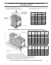
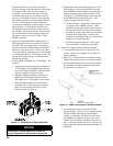
If the sections still do not appear to be drawn
metal to metal, use feeler gauge provided to
measure any gaps at the locations identied in
Figure 8. (Unless specied otherwise, gaps
should
be measured at these locations). A
maximum gap of .025” is acceptable.