


59
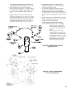
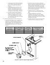
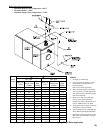
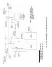
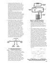
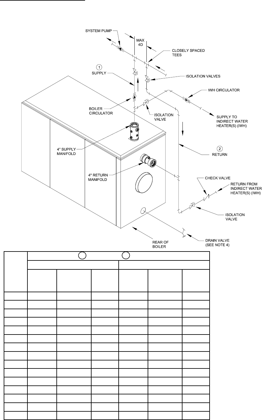
Figure 49a: Recommended MPC Minimum Piping - Single Boiler Application
NOTES:
1. All piping is schedule 40.
2. Pipe sizes listed are based on a 20°F
or 40°F Delta T (temperature rise
across the boiler).
Select one to match application.
3. When specied supply/return piping
size is less than 4”, install appropriate
size reducer directly onto boiler supply
and return manifolds.
4. Drain valve - ball valve preferable,
gate valve acceptable alternative
(supplied by others). Minimum valve
size per ASME Code is 3/4” NPT.
5. Swing joints may be piped over the top
of the boiler if space is limited.
6. System design must accommodate the
above Boiler Operating Requirements.
7. Diaphragm expansion tank shown, but
other types of air elimination systems
may be used.
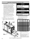
Boiler
Model
Supply / Return
20°F Rise 40°F Rise
Nom. I.D.
(Inch)
Water Side
Press. Drop
(Ft/Wtr)
Flow
Rate
(GPM)
Nom. I.D.
(Inch)
Water Side
Press. Drop
(Ft/Wtr)
Flow
Rate
(GPM)
MPC4 2 1.9 42.4 1½ 0.9 21.2
MPC5 2 2.6 65.2 1½ 1.6 32.6
MPC6 2 3.3 83.7 1½ 2.3 41.9
MPC7 2½ 4.0 102.3 1½ 3.0 51.2
MPC8 2½ 4.7 120.9 2 3.7 60.5
MPC9 3 5.4 139.6 2 4.4 69.8
MPC10 3 6.1 158.1 2 5.1 79.0
MPC11 3 6.8 176.7 2 5.8 88.3
MPC12 3 7.5 195.2 2½ 6.4 97.6
MPC13 4 8.2 213.8 2½ 7.1 106.9
MPC14 4 8.9 232.3 2½ 7.8 116.1
MPC15 4 9.6 250.9 2½ 8.5 125.5
MPC16 4 10.3 269.5 3 9.2 134.8
MPC17 4 11.0 288.1 3 9.9 144.1
MPC18 4 11.7 306.6 3 10.6 153.3
1
2