


43
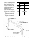
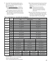
Table X: Jacket Top Corner / Intermediate Panel Arrangement
Boiler Size
Side of
Boiler
Order of Assembly (* See Panel Designation Below)
Front f Block Assembly g Rear
4 Section
Left 27” TCP w/J 6¾” TCP w/H
Right 6¾” TCP w/H 27” TCP w/J
5 Section
Left 33¾” TCP w/J 6¾” TCP w/H
Right 6¾” TCP w/H 33¾” TCP w/J
6 Section
Left 40½” TCP w/J 6¾” TCP w/H
Right 6¾” TCP w/H 40½” TCP w/J
7 Section
Left 27” TCP w/J 27” TCP w/H
Right 27” TCP w/H 27” TCP w/J
8 Section
Left 33¾” TCP w/J 27” TCP w/H
Right 27” TCP w/H 33¾” TCP w/J
9 Section
Left 33¾” TCP w/J 33¾” TCP w/H
Right 33¾” TCP w/H 33¾” TCP w/J
10 Section
Left 40½” TCP w/J 33¾” TCP w/H
Right 33¾” TCP w/H 40½” TCP w/J
11 Section
Left 40½” TCP w/J 40½” TCP w/H
Right 40½” TCP w/H 40½” TCP w/J
12 Section
Left 34¾” TCP w/J 27” TIP w/J 27” TCP w/H
Right 27” TCP w/H 27” TIP w/J 34¾” TCP w/J
13 Section
Left 34¾” TCP w/J 27” TIP w/J 33¾” TCP w/H
Right 33¾” TCP w/H 27” TIP w/J 34¾” TCP w/J
14 Section
Left 34¾” TCP w/J 33-¾” TCP w/J 33¾” TCP w/H
Right 34¾” TCP w/H 33¾” TIP w/J 34¾” TCP w/J
15 Section
Left 40½” TCP w/J 33¾” TIP w/J 33¾” TCP w/H
Right 33¾” TCP w/H 33¾” TIP w/J 40½” TCP w/J
16 Section
Left 40½” TCP w/J 33¾” TIP w/J 40½” TCP w/H
Right 40½” TCP w/H 33¾” TIP w/J 40½” TCP w/J
17 Section
Left 33¾” TCP w/J 27” TIP w/J 27” TIP w/J 33¾” TCP w/H
Right 33¾” TCP w/H 27” TIP w/J 27” TIP w/J 33¾” TCP w/J
18 Section
Left 33¾” TCP w/J 33¾” TIP w/J 27” TIP w/J 33¾” TCP w/H
Right 33¾” TCP w/H 27” TIP w/J 33¾” TIP w/J 33¾” TCP w/J
* Panel Designations:
TCP w/J = Top Corner Panel w/ Joiner Bracket
TCP w/H = Top Corner Panel w/ Holes
TIP w/J = Top Intermediate Panel w/ Joiner Bracket
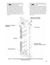
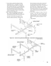
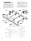
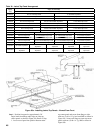
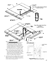
Locate Jacket Top Corner Panels packed in carton
marked ‘JC-2’. Install Jacket Top Corner Panels per
order of assembly shown in Table X, also refer to
illustration in Figure 26.
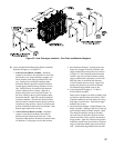
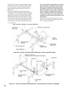
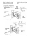
On 4 thru 6 Section Boilers, assemble top
corner panel #1 to 6¾” top corner panel #2 using
two (2) #8 x ½” lg. hex head sheet metal screws,
before installing on frame rails as noted in Step 2.
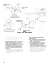
Starting on the left side, at the front, secure
top corner panel #1 to front horizontal and vertical
frame rails with two (2) #8 x ½” lg. hex head sheet
metal screws (SMS).
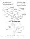
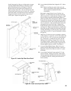
Secure top corner panel #1 to next set of frame
rails with two (2) #8 x ½” lg. SMS, see Figure 26,
Detail A. If necessary, push or pull frame rails to
align holes.
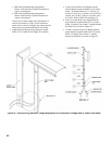
NOTE: Like the lower tie bars installed
previously, these top corner panels
maintain the proper distance between
frame rails for assembly of remaining
jacket panels.
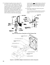
On 7 thru 11 Section Boilers, locate top corner
panel #2 per Table X and secure to panel #1 using
two (2) #8 x ½” lg. hex head SMS. Align mounting
holes in panel #2 with holes in frame rails and
secure with two (2) #8 x ½” lg. hex head SMS.