


26
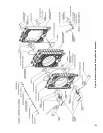
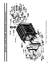
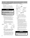
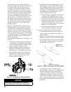
INSTALL COMMON PARTS TO BLOCK
ASSEMBLY, Refer to Figure 9.
1. Remove contents from Common Parts Carton
marked ‘CPC’.
2. Locate four (4) C. I. burner swing door (BSD)
hinge/latch castings, two (2) C. I. BSD hinge loop
castings, ten (10) 7/16 split lock washers and ten
(10) 7/16 -14 x 1-1/2 lg. cap screws.
NOTICE
Front section and burner swing door (BSD) are
designed to use universal parts that can be
mounted to make the hinge set work for either
left hand or right hand swing.
For the purpose of these instructions, Burnham
will default to mounting hinge set for left hand
swing (left side).
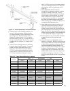
3.
Determine best hinge arrangement for your
installation based on room size, piping arrangement,
burner, fuel lines, utilities and service clearances.
4. For BSD left hand swing (left side hinge) -
a. Install hinge/latch castings, pin side up, on hinge
pads located on left side of front section. Use
two (2) 7/16” split lock washers and two (2)
7/16 -14 x 1-1/2 lg. cap screws per hinge pin,
see Figures 9 and 10. Secure hardware wrench
tight.
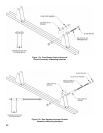
b.
Install hinge/latch castings, latch side up, on
hinge pads located on right side of front section
using same hardware for hinge latch as was
used for hinge pin, see Figures 9 and 10. Secure
wrench tight.
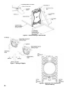
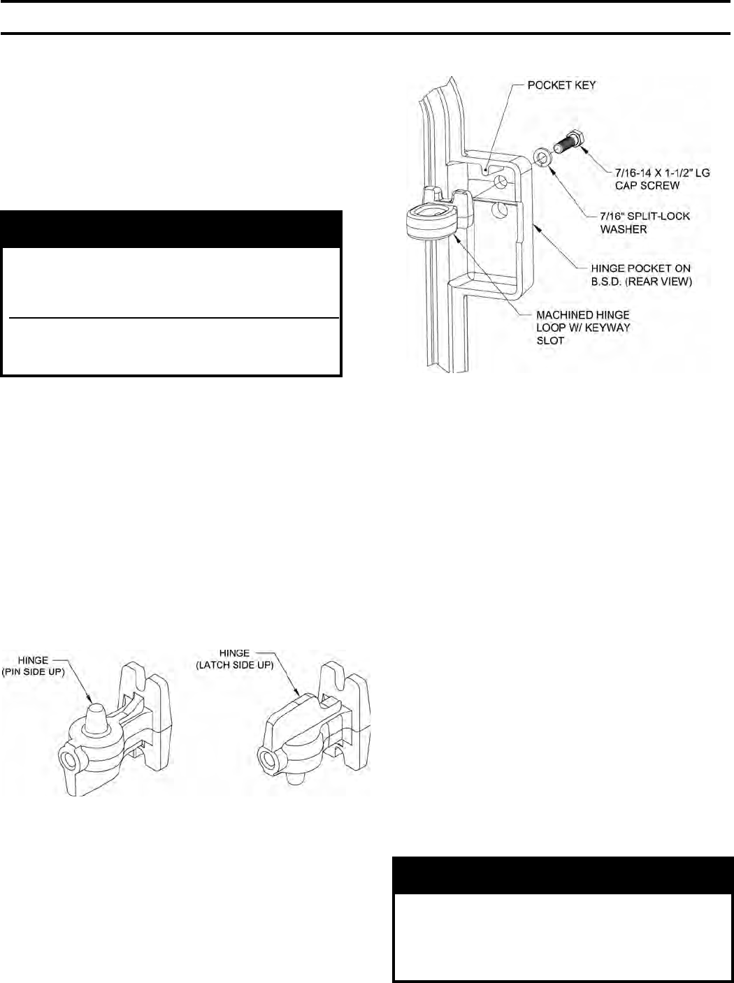
Figure 10: Universal Hinge/Latch Casting
c.
Locate and position burner swing door (BSD)
vertically against wall or structure to allow
access to both side, front and rear (insulation
side).
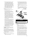
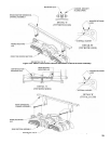
d. Install hinge loops inside hinge pockets located
on left side of BSD by engaging keyway slot in
loop over pocket key to lock position, see Figure
11. Attach each hinge loop with one (1) 7/16”
split lock washer and one (1) 7/16 -14 x 1-1/2”
lg. cap screw, secure hardware wrench tight.
Figure 11: Hinge Loop
5. For BSD right hand swing (right side hinge) -
a. Repeat 4a thru 4d but install hinge set and
hardware in reverse locations for right hand
swing.
6.
Complete Burner Swing Assembly (BSD) - see
Figure 9.
a. Install BSD rope gasket to rear of door.
b. If necessary, clean the rope groove around
perimeter of the BSD with a wire brush.
c. Using the multi-purpose spray adhesive
provided, apply the adhesive to the perimeter
rope groove. Follow the directions on the can
for application and tack time.
d. Locate a 158” length of silicone coated berglass
rope from common parts carton. Starting at
3 o’clock position, push rope into groove and
continue around perimeter until rope overlaps the
starting point. Rope should be approximately
4” longer than required. Use a permanent black
marker to mark the rope approximately 1/8”
beyond point of overlap. Cut off excess with
scissors or utility knife and wooden cutting
block.
e. Apply a generous bead of red sealant to both
ends of cut rope, push ends together and smooth
excess sealant over joint with your nger.
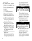
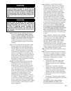
WARNING
Sealant must be properly applied to ALL boiler
joints. Failure to properly seal the boiler joints
will result in combustion gas leaks through the
joint. DO NOT operate boiler with combustion
gas leaks.
SECTION III - BOILER ASSEMBLY INSTRUCTIONS (KD Boiler) - Continued