


52
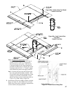
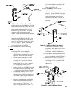
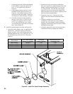
1. Harness is split into two (2) 7 wire bundles that exit
side of front panel as shown in Figure 25.
2. Each seven (7) wire harness bundle must be encased
in exible conduit from cover plate to burner control
panel or junction box.
3. Locate front panel cover plates in JC-1 carton.
4. Determine routing, length and type of ‘BX’
connectors to be used on exible conduit.
5. Mount ‘BX’ connector and exible conduit to
one (1) front panel cover plate. Pull wire bundles
through conduit.
6. Secure cover plate to side of jacket front panel using
(2) #8 x 1/2” lg. hex head SMS.
7. Locate and install one (1) plastic hole plug
(provided) into unused 7/8” dia. hole in cover plate.
8. Install remaining cover on opposite side of front
panel. Secure with #8 x 1/2” lg. hex head SMS,
push (3) plastic hole plugs into 7/8” dia. holes.
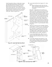
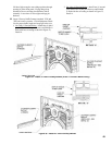
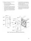
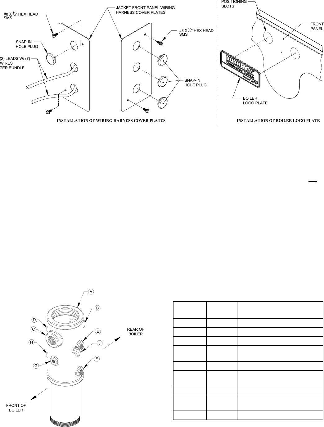
Figure 37: Install Jacket Front Panel Harness Cover Plates and Logo Plate
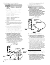
9. Connect other end of exible conduit to burner
control panel or junction box. Connect control/
safety circuit wires to appropriate terminals per
wiring diagram provided with burner.
Install Logo Plate on Jacket Front Panel if Optional
Jacket Split Burner Swing Door Cover Panels are not to
be used.
Locate Logo Plate shipped in Instruction Envelope.
Peel paper off adhesive strips and install by inserting
positioning tabs on rear of Logo Plate into slotted
openings located at top of front panel shown in Figure
37.
If optional BSD cover panels are used, Logo Plate will
be installed on the cover as instructed in later steps.
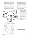
Locate Water Trim and Control Carton marked ‘WT’
and remove contents. Check Equipment Check List for
proper working pressure/relief valve. Install standard
trim and controls as follows:
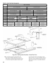
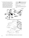
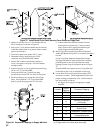
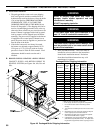
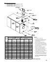
1. See Figure 38 for purpose of tappings on supply
manifold.
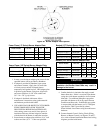
Figure 38: Purpose of Tappings in Supply Manifold
* Location
Size of
Tapping
Purpose of Tapping
A 4” Flange Supply
B 1½” Relief Valve
C 1½” Auxiliary Tapping (Plug)
D ¾”
Operating Temperature
Limit Control
E ¾” Probe L.W.C.O.
F ¾”
High Temperature Limit Control /
Manual Reset
G ½” Temperature / Pressure Gauge
H ¾”
Low / High / Low
or Modulating Control
J ½ Low Fire Hold Control
* Supply Manifold must be installed with 1½” coupling ‘B’
or ‘C’ aligned with front of boiler when water tight.