


18
Then proceed to Step C of this section on Page 24,
“HYDROSTATIC TEST”.
FIELD ASSEMBLED SECTIONS - If the boiler was
ordered knockdown, to be eld assembled, follow the
assembly procedure outlined on the following pages.
1. ASSEMBLY OF SECTIONS
These sections are designed to be drawn together
one section at a time using the Manual Draw-up Kit
(Burnham P/N 102008-01 or P/N 102008-02) using
ordinary hand tools.
Tools required:
(1) ¾” Drive Ratchet
(1) 1¼” Socket
(1) 1¼” Combination or Open End Wrench
(1) Can Thread Cutting Oil or Grease
WHEN ASSEMBLING SECTIONS WITHOUT
HYDRAULIC DRAW-UP EQUIPMENT, IT
IS RECOMMENDED THAT ONE SECTION
BE ASSEMBLED AT A TIME. NEVER
ASSEMBLE MORE THAN TWO SECTIONS
AT A TIME.
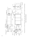
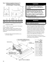
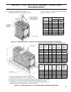
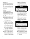
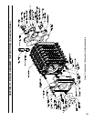
Assembly Procedure (refer to Figure 5 for Exploded
View of Block Assembly and Draw-up Hardware):
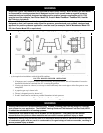
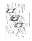
Place the rear section in its approximate
nal position, as outlined in Section I. Stand rear
section up and brace in vertical position with a
suitable prop. See Figure 6.
Clean the rope groove around perimeter of
the rear section with a wire brush.
Open the Boiler Assembly Carton(s),
marked ‘BAC’ and remove contents. Separate
the items by type. There are two (2) different
pre-cut lengths of the red silicone coated
berglass rope. The combustion chamber rope is
86” long and the perimeter rope is 164” long.
Using the multi-purpose spray adhesive
provided, apply the adhesive to the perimeter
rope groove. Follow the directions on the can
for application and tack time. GREAT CARE
MUST BE TAKEN TO ENSURE THAT
THE ADHESIVE DOES NOT COME
IN CONTACT WITH THE MACHINED
NIPPLE PORTS.
While the adhesive is becoming tacky, clean
the nipples ports and nipples thoroughly with a
de-greasing solvent.
Locate a 164” length of silicone coated
berglass rope and 10.3 oz. cartridge of RTV
6500 or RTV 736 Red Silicone Sealant. Starting
at 3 o’clock position, push rope into groove and
continue around perimeter until rope overlaps
the starting point. Rope should be approximately
4” longer than required. Use a permanent black
marker to mark the rope approximately 1/8”
beyond point of overlap. Cut off excess with
scissors or utility knife and wooden cutting
block. Apply a generous bead of red sealant to
both ends of cut rope, push ends together and
smooth excess sealant over joint with your nger.
WARNING
Sealant must be properly applied to ALL boiler
joints. Failure to properly seal the boiler joints
will result in combustion gas leaks through the
joint. DO NOT operate boiler with combustion
gas leaks. The sealant should be applied before
each section is placed on the assembly.
Use the Loctite #592 lubricant supplied to
lubricate the nipples and nipple ports. Apply
the lubricant to the nipples and nipple ports,
then use a brush to disperse it evenly around the
nipples and nipple ports. Use approximately 20
ml of lubricant per ueway [(1) 7” and (1) 3”
nipple
and their corresponding nipple ports - (2)
in the rear section and (2) in the next adjoining
section].
Drive nipples squarely into section using
block of wood and hammer, or preferably, an
aluminum head hammer. Burnham offers a
polyethylene block for setting the nipples (part
no. 8052601). Place block over entire nipple
edge and hit the wood or polyethylene block
with the hammer.
NOTICE
Nipples must be driven in evenly and to the
proper depth to assure tight joints. Most nipple
leaks are caused by tilted or cocked nipples.
DO NOT use steel/iron head hammer to drive
nipples without using a wood or polyethylene
block. Nipple damage may result.
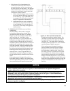
A special nipple setting gauge is provided
for the nipples. Gauge nipple at 90° angles to
insure that it is driven to the proper depth into
the nipple opening (nipple port). Cut-out in
gauge must rest on nipple, with the legs of the
gauge touching nished face of section, when
nipple
is properly driven. See Figure 7.
Apply a generous bead of RTV 6500 or RTV
736 sealant to the (4) ueway sealing grooves on
rear
section. Sealant should start against the rope
gasket, run across the groove in one continuous
bead, and end against rope gasket at the opposite
side. Refer to Figure 5.