


31
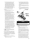
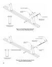
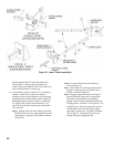
5. Add front/center section mounting hardware to all
but one (1) horizontal support channel assembly.
Lay channel assembly on oor with brackets facing
up, see Figure 17a. Install hardware as shown
with two (2) washers and two (2) 1/2” lg. spacers
between bracket legs and one (1) washer and one (1)
hex nut on each end of 3/8” -16 x 3-1/4” lg. rod, see
assembled end view in Figure 17a. Repeat for all
brackets.
6. Add rear section mounting hardware to remaining
horizontal support channel assembly. Lay channel
assembly on oor with brackets facing up, see
Figure 17b. Install hardware as shown with one
(1) 1-3/4” lg. spacer between bracket legs, one (1)
washer and one (1) hex nut on one end of 3/8” -16
x 13-3/8” lg. threaded rod, with one (1) washer,
one (1) 2-5/8” lg. spacer, two (2) washers and one
(1) hex nut on the opposite end of rod. Repeat for
second bracket, refer to assembled end view in
Figure 17b.
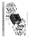
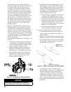
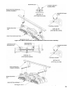
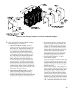
7. Mount horizontal channel
assembly(lies) to appropriate casting(s) on block
assembly as outlined in Table VIII. Position
threaded rods on channel assemblies over slotted
lugs on casting as shown in Figure 18a. Spread
inside washers until rod drops to bottom of slot
as shown in Figure 18a, Detail ‘A’. Hand tighten
nuts, make sure washers engage casting below
washer retaining lugs, see Detail B. Repeat for all
remaining bracket attachment points.
8. Mount rear
horizontal channel assembly to rear
section and adjacent center section as shown in
Figure 18b. Position assembly behind supply
manifold, spread washers and lower threaded rod
into slotted openings on both castings as shown in
Figure 18b, Detail A. Hand tighten nuts, make sure
washers engage casting below washer retaining lugs
as shown in Detail B. Repeat for opposite side.
9. Wrench tighten hex nuts on all channel assemblies
making sure rods are fully seated in slotted
openings.
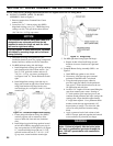
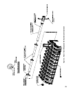
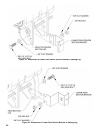
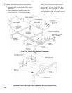
10. Locate and install lower section
brackets to casting legs. Brackets are universal and
can be used on either side of block assembly. Refer
to Table VIII for appropriate casting leg to be used
for bracket attachment. Brackets mount to rear
surface of leg with offset toward the rear as shown
in Figure 19. Hold bracket at a 45° angle while
engaging upper slot over threaded tie rod, rotate
bracket around rod until lower slot is aligned with
lower hole in casting leg. Insert 5/8 -11 x 2” lg.
bolt with washer through cast hole in leg and slot in
bracket.
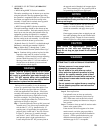
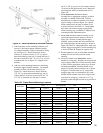
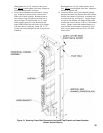
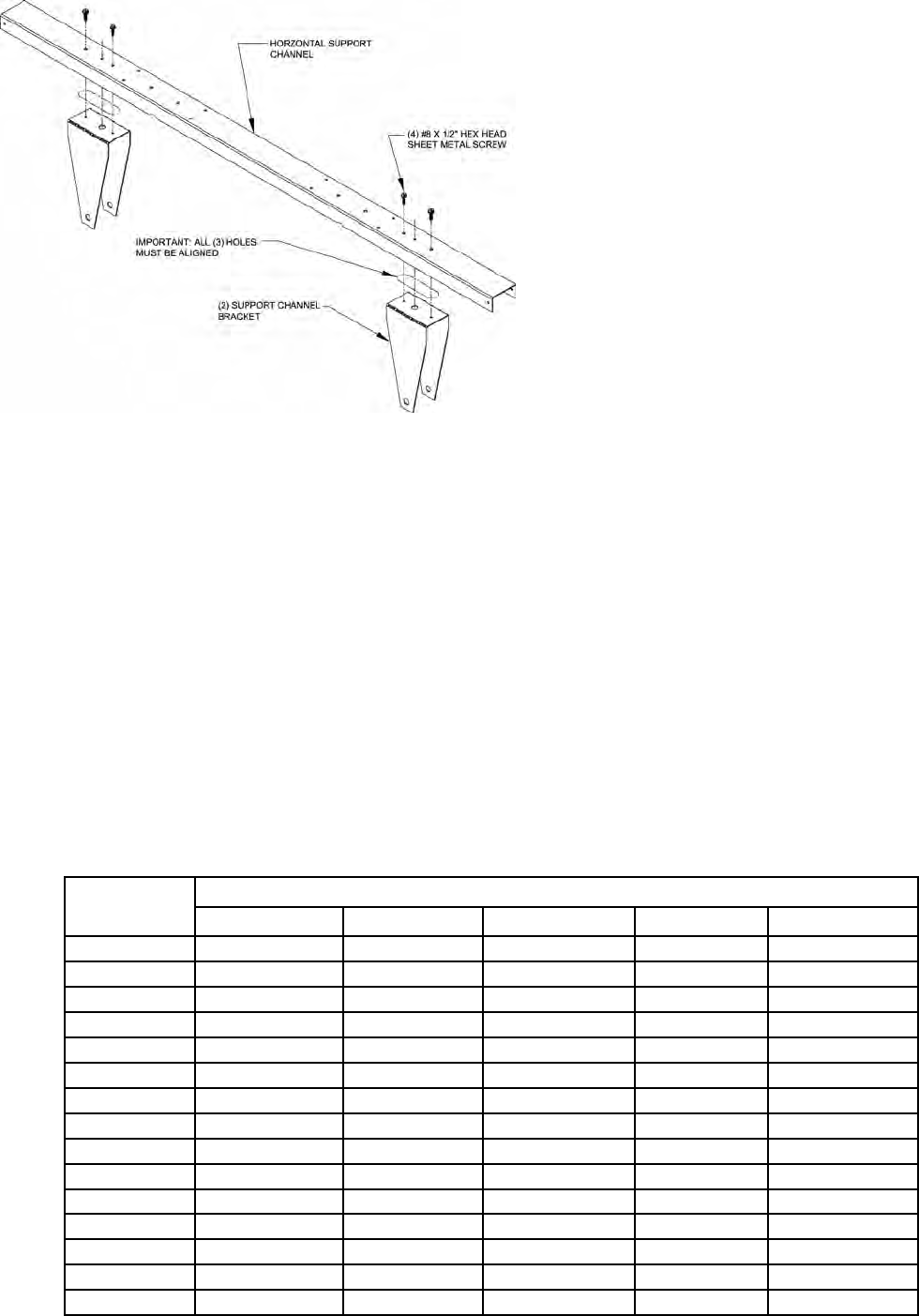
Figure 16: Secure Brackets to Horizontal Channel
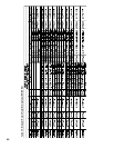
Boiler Size
Front f Block Assembly g Rear
Frame 1 Frame 2 Frame 3 Frame 4 Frame 5
4 Section Front Section Rear Section ----- ----- -----
5 Section Front Section Rear Section ----- ----- -----
6 Section Front Section Rear Section ----- ----- -----
7 Section Front Section Section 4 Rear Section ----- -----
8 Section Front Section Section 5 Rear Section ----- -----
9 Section Front Section Section 5 Rear Section ----- -----
10 Section Front Section Section 6 Rear Section ----- -----
11 Section Front Section Section 6 Rear Section ----- -----
12 Section Front Section Section 5 Section 9 Rear Section -----
13 Section Front Section Section 5 Section 9 Rear Section -----
14 Section Front Section Section 5 Section 10 Rear Section -----
15 Section Front Section Section 6 Section 11 Rear Section -----
16 Section Front Section Section 6 Section 11 Rear Section -----
17 Section Front Section Section 5 Section 9 Section 13 Rear Section
18 Section Front Section Section 5 Section 10 Section 14 Rear Section
Table VIII: Frame/Bracket Mounting Locations