


51
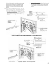
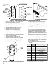
1. In most cases the burner adapter plate carton for the
specied burner will be provided by Burnham.
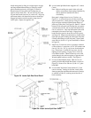
2. If adapter is provided by Burnham, open carton
and remove contents. Apply four (4) small dabs
of silastic on rear surface of adapter plate to
temporarily hold gasket in place. Hold adapter plate
in position against burner swing door, align holes
and secure with four (4) 3/8” lock washers and
3/8” - 16 x 7/8” lg. cap screws.
3. If adapter is furnished with burner, follow
manufacturer’s instructions using gasket material
and hardware provided with burner.
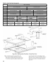
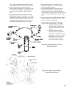
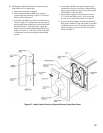
4. USE A HOLE SAW OR KNIFE TO CUT BURNER
SWING DOOR INSULATION TO MATCH
HOLE SIZE ON BURNER ADAPTER PLATE.
After cutting, remove any and all loose pieces of
insulation which may become lodged or interfere
with the head of the burner air tube after insertion.
5. Secure burner to adapter plate with four (4) ½” lock
washers and four (4) ½” - 13 hex nuts provided.
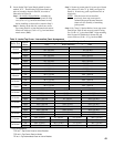
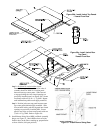
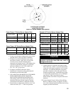
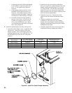
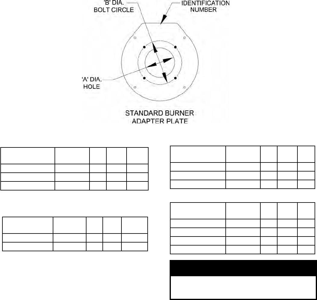
Figure 36: Burner Adapter Plate Options
Boiler Model Part No. I.D.
No.
‘A’ ‘B’
MPC4 thru MPC7 602263401 40 7-1/2 10-1/4
MPC8 thru MPC14 602263411 41 9 12
MPC15 thru MPC18 602263421 42 10-3/8 14-1/8
Power Flame (‘C’ Series) Burner Adapter Plate
Boiler Model Part No. I.D.
No.
‘A’ ‘B’
MPC4 thru MPC7 602263451 45 6-3/8 10-1/4
MPC8 thru MPC11 602263461 46 8-3/8 11-11/16
Power Flame (‘JR’ Series) Burner Adapter Plate
Boiler Model Part No. I.D.
No.
‘A’ ‘B’
MPC4 thru MPC7 602263001 00 6-3/4 10
MPC8 thru MPC15 602263011 01 8-1/4 10
MPC16 thru MPC18 602263021 02 10-1/4 11
Beckett (‘CF’ Series) Burner Adapter Plate
Boiler Model Part No. I.D.
No.
‘A’ ‘B’
MPC4 and MPC5 602263031 03 5 10
MPC6 and MPC7 602263041 04 6 10
MPC8 thru MPC11 602263071 07 7-1/4 10
MPC12 thru MPC18 602263081 08 8-1/8 11
Beckett (‘CG’ Series) Burner Adapter Plate
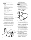
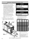
CAUTION
Failure to properly ll all gaps between the
insulation and burner blast tube may result in
damage to the burner.
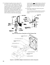
6. Conrm that hole in insulation ts snugly around
burner
blast tube. If hole is oversized, open burner
swing door (with burner attached) to access burner
blast tube. Use additional berglass rope gasket
provided with burner to ll in any space between
insulation and blast tube. If additional rope gasket
is not provided with the burner, use 3/8” berglass
rope rated for 2300°F (provided by others).
When nished, close burner swing door and secure
hardware.
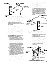
Connect Internal Control / Safety Circuit Wiring
Harness to Burner Controls, see Figures 25 and 37.
Also, refer to Burner Installation Manual and wiring
diagrams provided with burner.