


30
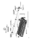
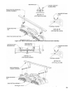
Repeat this process for each joint, securing the
previous assembly to the tube shown in next column
to the right in Table VII, also refer to Figure 13
for details. If space behind the boiler is limited,
on RWMT’s having two or more tubes, it may be
necessary to assemble the end cap to the adjoining
tube and then insert the assembly, capped end rst,
into the 4” NPT tapping on the back of the rear
section before joining the remaining tube(s). Allow
approximately 1½” of the tube to protrude from
the tapping, so that the next tube can be secured to
the assembly. Once the next tube is secured, insert
the assembly further into the tapping. Repeat this
procedure as necessary for up to seven (7) tube
RWMT assemblies.
4. Insert the completed RWMT assembly into the 4”
NPT tapping until the end cap reaches the front of
the boiler. The front support clip on the end cap
must rest on the internal shelf inside of the upper 3”
NPT boss on the front section. If necessary, insert
a long screw driver, wooden dowel or a short length
of 1/2 pipe through the 3” NPT tapping and into the
support collar on the end cap to lift and maneuver
the tube into position.
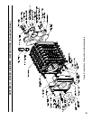
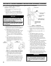
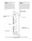
5. Install CI Return Manifold and 4” NPT Nipple - See
Figure 9.
a. Apply thread-sealing compound to both ends of
4” NPT nipple and hand tighten nipple into one
end of the CI Return Manifold (return manifold
casting is symmetrical about the ends).
b. Slide the CI Return Manifold Assembly over
RWMT, and install the threaded end of the 4”
NPT nipple into 4” NPT tapping in rear section.
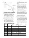
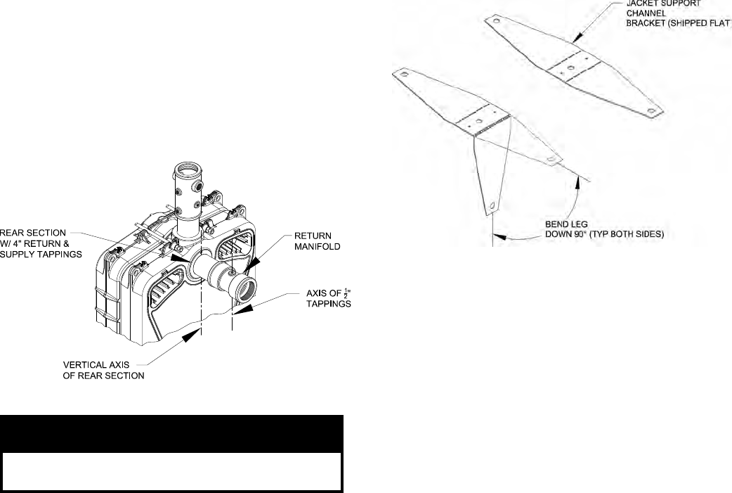
c. Wrench CI Return Manifold Assembly until
watertight and ½” NPT tappings (positioning
plugs) are aligned with vertical axis of rear
section as shown in Figure 14.
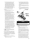
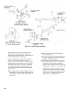
6. Thread upper and lower positioning plugs into 1/2”
NPT tappings. If necessary, push forward or pull
back on RWMT assembly and/or rotate until pins on
positioning plugs engage alignment holes in tube,
see Figure 13. Wrench both plugs until water tight.
7. Install RWMT front support plug into 3” NPT
tapping on upper front section boss.
a. Looking through 3” tapped hole, check position
of support collar on RWMT end cap. Collar
should be located approximately in the center of
the tapped hole both vertically and horizontally.
b. If necessary, adjust support collar position before
installing front support plug. For horizontal
adjustment, bend support clip up or down per the
amount of visual mis-alignment.
c. Thread front support plug into 3” NPT upper
front section boss, wrench plug water tight.
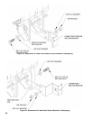
Install Jacket Support Frame to Block Assembly.
1. Locate Jacket Frame Carton(s), marked ‘JF’ and
remove contents, see equipment list on Page 3 for
quantity required.
2. Open “JF-P” Jacket Frame Parts Carton(s), packed
inside Jacket Frame Carton(s), and remove contents.
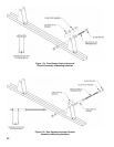
3. Locate support channel brackets which are shipped
at and need to be hand formed by bending both
legs down 90°, see Figure 15.
Figure 14: Orientation of Return Manifold
NOTICE
Orientation of return manifold is critical for
proper alignment of return water mixing tube.
Figure 15: Hand Form Support Channel Bracket
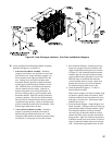
4. Locate horizontal support channels and FH-1
Hardware Bag(s). Position two (2) support channel
brackets on oor and place horizontal support
channel over brackets. All three (3) holes in both
parts be in alignment, if they are not, rotate
bracket. Secure brackets to channel using four (4)
#8 x 1/2 hex head sheet metal screws, see Figure 16.
Repeat until all horizontal channels and brackets are
assembled.