


105
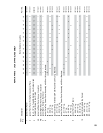
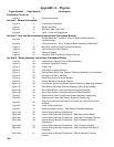
Figure Number Page Number Description
Section III - Boiler Assembly Instructions (Knockdown Boiler) (continued)
Figure 25 42 Internal Wiring Harness - Length Adjustment for Penetration Through Side
of Jacket Front Panel
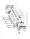
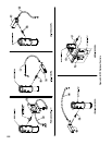
Figure 26 44 Install Top Corner/Intermediate Panels
Figure 27 44 Install Jacket Front Panel
Figure 28 45 Jacket Split Rear Panel Detail
Figure 29 45 Install Jacket Split Rear Panel
Figure 30a 46 Installing Jacket Top Panels - Viewed From Front
Figure 30b 47 Install Jacket Top Panels - Viewed From Rear
Figure 30c 47 Install Jacket Rear Top Panel - Viewed Front Rear
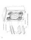
Figure 31 47 Install Burner Swing Door
Figure 32 49 Install 3rd Pass Flueway Bafes (4 thru 11 Section Boilers Only)
Figure 33 49 Install 2nd Pass Flueway Bafes
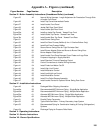
Figure 34 50 Secure Burner Swing Door for Tight Perimeter Seal
Figure 35 50 Install Burner Adapter Plate and Burner to Burner Swing Door
Figure 36 51 Burner Adapter Plate Options
Figure 37 52 Install Jacket Front Panel Harness Cover Plates and Logo Plate
Figure 38 52 Purpose of tappings in Supply Manifold
Figure 39 53 Install Standard Trim and Operating Control
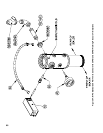
Figure 40 53 Control Connections to Internal Wiring Harness
Figure 41 54 Install Probe Low Water Cut-Off
Figure 42 54 Install High Limit Control
Figure 43 55 Install Modulation Control
Figure 44 55 Install Low/High/Low Control
Figure 45 55 Install Modulation Control
Figure 46 56 Install Flue Outlet Damper Assembly
Figure 47 57 Install Jacket Panels for Optional Burner Swing Door Cover
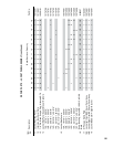
Section IV - Installation Instructions
Figure 48 58 Packaged Boiler Shipping Information
Figure 49a 59 Recommended MPC Minimum Piping - Single Boiler Application
Figure 49b 60 Recommended MPC Minimum Piping - Multiple Boiler Application
Figure 50a 61 Alternate MPC Minimum Piping - Single Boiler Application
Figure 50b 62 Alternate MPC Minimum Piping - Multiple Boiler Application
Figure 51 63 Parallel Piping Conversion
Figure 52 63 Typical Burnham Boiler - Primary-Secondary Loop System
Figure 53 63 Recommended Piping for Combination Heating & Cooling (Refrigeration)
Systems
Figure 54 64 Discharge Piping for Pressure Relief Valve
Section V - Operating Instructions
Section VI - Service Instructions
Section VII - Burner Specications