


56
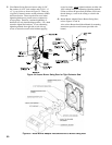
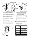
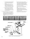
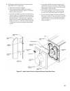
v. Connect opposite end of T991A Modulating
Control harness to right side junction box
cover ‘A’, hole location #4 as shown in
Figure 40.
vi. Locate mating connector labeled “LO-HI-
LO/MOD”
inside right junction box, see
Figure 40. Join mating connectors which
are polarized and lock together. Lightly tug
on connectors to make sure they are secure.
vii.
If no other controls are being installed at
this time, secure Cover ‘A’ and Cover ‘B’
to jacket rear top panel with two (2) #8 x
1/2” lg. hex head SMS per cover. Install
7/8” knockout plugs (provided) to all unused
holes, refer to Figure 40.
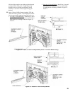
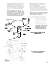
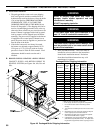
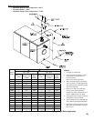
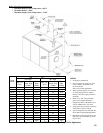
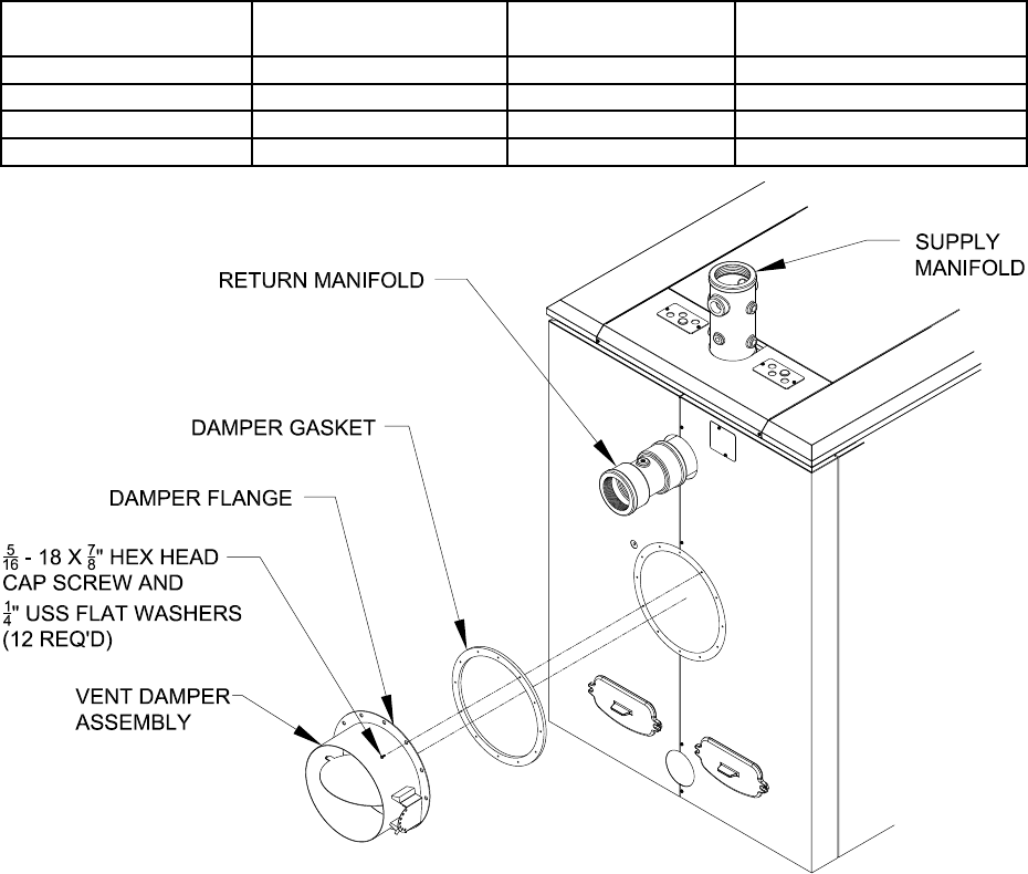
Install Flue Outlet Damper Assembly, see Figure 46.
1. Locate ue outlet damper carton, as applicable (see
Table below). Open carton remove a ue outlet
damper assembly, a ue outlet damper gasket and
mounting
hardware bag (12 pcs each 5/16 -18 x 7.8”
hex head plated cap screws and 1/4” USS plated
washers).
Figure 46: Install Flue Outlet Damper Assembly
2. Assemble two cap screw/washer combinations,
then, insert cap screws/washers through a ue outlet
damper
assembly-mounting ring at 3 o’clock and
9 o’clock positions. Place the ue outlet damper
gasket onto cap screws and position damper with
gasket onto boiler rear ue collector, aligning screws
with ue collector threaded holes.
3. Thread the screws at 3 o’clock and 9 o’clock
positions into ue collector threaded holes hand
tight.
4. Assemble remaining cap screw/washer
combinations, then, insert cap screws/washers
through a ue outlet damper assembly-mounting
ring/gasket and thread the screws into ue collector
threaded
holes hand tight.
5. Alternately tighten the screws with an open end or
socket head wrench to complete the assembly.
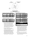
Boiler Model
Flue Outlet Damper
Carton Part Number
Flue Outlet
Damper Diameter
Recommended Vent
Connection Size
MPC4 & MPC5 102473-01 7” Dia. 7” Dia.
MPC6 thru MPC8 102473-02 8” Dia. 8” Dia.
MPC9 thru MPC12 102473-03 10” Dia. 10” Dia.
MPC13 thru MPC18 102473-04 12” Dia. 12” Dia.