


39
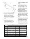
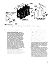
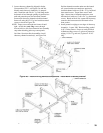
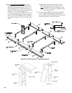
3. Locate chaseway channel(s) shipped in Jacket
Carton marked ‘JC-2’, see Figures 24c and 24d.
Identify main chaseway channel by it’s unequal
ends. Install the end with 8¼” lg. side ange under
horizontal rail and through openings in junction box
until end protrudes past rear horizontal channel.
Secure main chaseway channel to both horizontal
frame rails using #8 x 2½” lg. hex head sheet metal
screws as shown in Figure 24c.
NOTE: Torque screws through rear frame rail until
tight. At this time, screws through
forward rail(s) to allow movement in later assembly
steps when attaching jacket top corner panels.
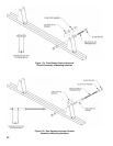
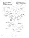
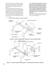
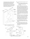
On 8 thru 18 sections block assemblies, install
chaseway channel extension(s), see Figure 24d.
Position channel extension under next horizontal
rail, secure bracket on extension to previously
installed channel with two (2) #8 x ½” lg. hex head
sheet metal screws. Torque these screws until
tight. Secure front of channel extension to next
horizontal rail with two (2) #8 x 2½” lg. sheet metal
screws. Based on block size, repeat until chaseway
extension has been secured to horizontal rail on
front section.
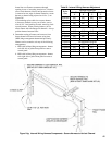
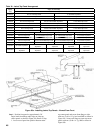
4. Install protective edging to raw edges of chaseway
channel(s) - Locate ‘JH-1’ Hardware Bag, packed
in JC-1 Jacket Carton. From raw stock provided
in Hardware Bag, cut two (2) pieces of protective
edging 1-13/16” lg. and two (2) pieces 4-11/16”
long.
Figure
24c: Internal Wiring Harness Components - Install Main Chaseway Channel
Figure 24d: Internal Wiring Harness Components - Install Chaseway Channel Extension(s)