


104
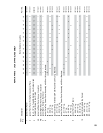
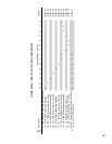
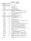
Figure Number Page Number Description
Equipment Check List
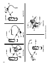
Figure 1a 2 Carton Identication
Section I - General Information
Figure 1b 10 Dimensional Information
Figure 2 14 Boiler Foundation
Figure 3a 15 MPC With Rear Outlet Vent
Figure 3b 16 Vents - Faults and Suggestions
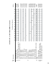
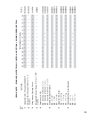
Section II - Cast Iron Block Assembly Instructions (Knockdown Boilers)
Figure 4a 17
Lifting Instructions - Limited to 4 thru 12 Section Block Assembly
(No Steel Base)
Figure 4b 17 Lifting Instructions - 4 thru 18 Section Block Assembly w/Steel Base
Figure 5 19 Manual or Hydraulic Draw-up Section Assembly
Figure 6 20 Vertical Bracing of Rear Section
Figure 7 20 Setting of Nipples
Figure 8 20 Inspection Pad Locations for Section Draw-up
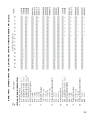
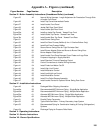
Section III - Boiler Assembly Instructions (Knockdown Boiler)
Figure 9 25 Installation of Common Parts to Block Assembly
Figure 10 26 Universal Hinge/Latch Casting
Figure 11 26 Hinge Loop
Figure 12 27 Orientation of Supply Manifold
Figure 13 29 Return Water Mixing Tube Reduced Clearance Assembly and Installation
Figure 14 30 Orientation of Return Manifold
Figure 15 30 Hand Form Support Channel Bracket
Figure 16 31 Secure Bracket to Horizontal Channel
Figure 17a 32 Front/Center Section Horizontal Channel Assembly w/Mounting Hardware
Figure 17b 32 Rear Section Horizontal Channel Assembly w/Mounting Hardware
Figure 18a 33 Mount Rear Section Horizontal Channel to Block Assembly
Figure 18b 33 Mount Rear Section Horizontal Channel to Block Assembly
Figure 19 34 Attachment of Lower Front/Center Section Bracket to Casting Leg
Figure 20 34 Attachment of Lower Rear Section Bracket to Casting Leg
Figure 21 35
Securing Frame Side Channels to Horizontal Top Channel and Lower
Brackets
Figure 22 36 Lower tie Bar Installation
Figure 23 37 Heat Exchanger Insulation - One Piece and Modular Wrappers
Figure 24a 38 Internal Wiring Harness Components
Figure 24b 38 Internal Wiring Harness Components - Mounting Junction Boxes
Figure 24c 39 Internal Wiring Harness Components - Install Main Chaseway Channel
Figure 24d 39 Internal Wiring Harness Components - Install Chaseway Channel
Extension(s)
Figure 24e 40 Internal Wiring Harness Components - Install Protective Edging
Figure 24f 40 Internal Wiring Harness Components - Install and Secure Harness to
Chaseway
Figure 24g 41 Internal Wiring Harness Components - Secure Harness to Vertical
Channel