


41
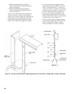
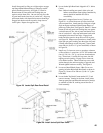
Figure 24g: Internal Wiring Harness Components - Secure Harness to Vertical Channel
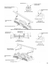
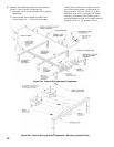
Insert rst set of harness connectors through
opening in rear of secondary junction box. Remove
excess slack between J-boxes until protective sleeve
is centered on raw edge of channel extension, secure
harness to channel using nylon wire tie No. 3, see
Figure 24f.
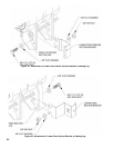
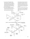
Use remaining nylon cable ties to secure harness
to chaseway channel at every set of holes, start at
wire tie No. 4 and working forward, removing slack
at each juncture. When securing harness, do not
allow contact with side anges on channels. Always
position
harness between holes.
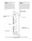
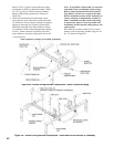
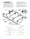
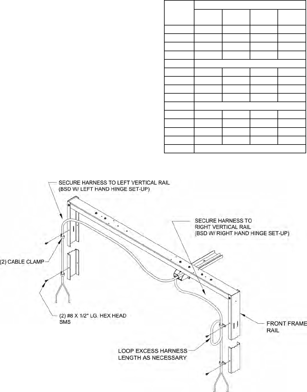
6. Determine routing of harness and secure to front
frame channel rails based on burner swing door
(BSD) hinge arrangement determined previously.
Harness can be secured to suit any of the following
arrangements:
a.
BSD with left hand hinge arrangement - harness
exits left side of jacket front panel en route to
control panel.
b. BSD with left hand hinge arrangement - harness
exits right side of jacket front panel en route to
control panel.
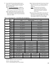
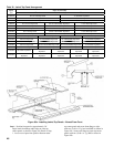
Boiler
Size
Harness Adjustment
Wire Tie
‘A’
Wire Tie
‘B’
Wire Tie
‘C’
Wire Tie
‘D’
4 Section CUT CUT CUT CUT
5 Section CUT CUT CUT ---
6 Section CUT CUT --- ---
7 Section CUT --- --- ---
8 Section No Adjustment Required
9 Section CUT CUT CUT CUT
10 Section CUT CUT CUT ---
11 Section CUT CUT --- ---
12 Section CUT --- --- ---
13 Section No Adjustment Required
14 Section CUT CUT CUT CUT
15 Section CUT CUT CUT ---
16 Section CUT CUT --- ---
17 Section CUT --- --- ---
18 Section No Adjustment Required
Table IX: Internal Wiring Harness Adjustment