


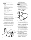
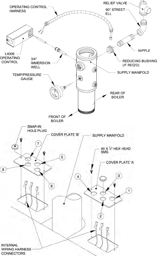
53
Note: Supply manifold must be installed with 1½”
couplings aligned with front and rear axis of boiler.
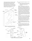
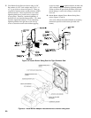
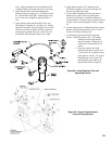
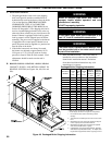
2. Apply thread sealant and install temperature/
pressure gauge into tapping ‘G’, see Figures 38 and
39. Wrench until water tight. Tighten gauge using
hex on stem, do not tighten or apply pressure to
case.
3. Apply thread sealant and install relief valve and
pipe ttings in Tapping ‘B’, see Figure 38. Fittings
should be arranged as shown in Figure 39. By code,
relief valve must be installed vertically. Based on
vent pipe arrangement and access, relief valve can
be installed with discharge facing a left or right.
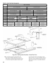
Figure 39: Install Standard Trim and
Operating Control
4. Apply thread sealant to 3/4” immersion well
and install in tapping ‘D’ as shown in Figure 38.
Wrench well until water tight.
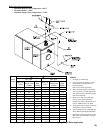
5. Locate L4006A Operating Control and remove
knockout on casing closest to mounting hole.
Connect end of harness with forked terminals to
casing knockout. Connect wires to terminal on limit
control, wires are interchangeable. Refer to Figure
39.
6.
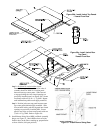
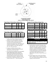
Connect opposite end of L4006A Operating Control
Harness to right side junction box cover ‘A’, hole
location #1 as shown in Figure 40.
7. Locate mating connectors labeled “operating
control” inside right junction box. Join mating
Figure 40: Control Connections to
Internal Wiring Harness
connectors
which are polarized
and lock together. Lightly tug on
connectors to make sure they are
secure.
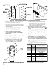
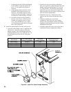
8.
If no other controls are being
installed at this time, secure Cover
‘A’ and Cover ‘B’ to jacket rear top
panel with two (2) #8 x 1/2” lg. hex
head SMS per cover. Install 7/8”
knockout plugs (provided) to all
unused holes, refer to Figure 40.