


21
WARNING
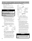
This is a forced draft red boiler and sealant must
be applied where specied for proper and safe
performance. Burnham Commercial has approved
section joint sealants (silastics) manufactured
by Dow-Corning under the product number RTV
736, and Sil-Bond under the product number RTV
6500.
WARNING
Sections must be drawn-up tight immediately
after properly applying sealant for best results.
Although sections may be joined within two
(2) hours of applying sealant, humidity and
temperature affect cure time. If a “thick skin” has
been formed on the sealant bead, remove and re-
apply sealant.
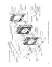
Position the next adjoining section to be
assembled,
.
Sections must always be assembled
so that the rope groove on one section mates
to the sealing tongue on the next section in the
assembly.
Clean and lubricate the nipple ports on the
mating (tongue) side of the adjoining section.
Place the nipple ports of the adjoining section
onto the nipples previously installed in the rear
section. To facilitate assembly, it is advisable
to enter the upper nipple rst in its port. Then
enter the lower nipple in it’s respective port. If
necessary, place a lifting bar (crowbar) under the
center of the section and lift the nipple port onto
the upper nipple. Drive section in place with a
heavy block of wood, striking blows as squarely
as possible over nipple ports.
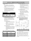
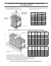
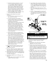
From Manual Draw-up Kit, locate and
assemble two (2) sets that include a ¾” x 23”
lg. threaded rod, 6½” dia. pressure plate, ¾”
at washer and ¾” hex nut as shown in Figure
5. Insert one assembly through each of the 3”
and 4” NPT bosses on rear section until pressure
plate is tight against the boss. Locate and place
the 8¾” dia. pressure plate on the opposite end
of threaded rod in upper nipple port. Place
remaining 6½” dia. pressure plate on rod
protruding through lower nipple port. Install a
¾” washer, ¾” coupling spacer, ¾” washer and
¾” hex nut on each rod. Center upper pressure
plates on nipple port and boss while tightening
nut until tension holds assembly in place. Repeat
for lower assembly. Refer to Figure 5 to verify
proper arrangement.
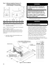
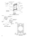
DRAW UP SECTION SLOWLY
AND EVENLY. When you start, machined
surfaces between adjoining sections should
be approximately 3/8” to 1/2” apart. The 7”
nipple will pull harder than the 3” nipple. If
two (2) people are pulling simultaneously,
stop periodically to verify that gaps between
adjoining sections are equal at both nipple
ports. If not, pull the nipple with the larger
gap until equal before proceeding. Continue
draw-up, paying close attention to the nipple
lubricant as it squeezes when the sections come
in close contact. The lubricant should continue
to squeeze out until the sections are connected
metal to metal at the designated inspection
pads shown in Figure 8.
(Unless specied otherwise, gaps should be only
measured at these locations). A maximum gap
of .025”.
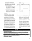
KEEP NIPPLES ALIGNED WITH NIPPLE
PORTS. If necessary, tap edge of nipples lightly
with a blunt tool or rod to keep nipples from
cocking while sections are being drawn-up.
DO NOT DRAW UP SECTION WHEN
NIPPLES ARE COCKED. If the torque
required becomes excessive, periodically place a
heavy block of wood over each nipple port and
strike as squarely as possible with several blows
to relieve tension on the draw-up rods.
Remove Draw-up Rod Assemblies and set
aside.
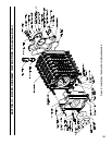
Prepare center section on block assembly
to receive next casting, see Figure 5. Clean the
rope grooves around the combustion chamber
and perimeter of the section with a wire brush.
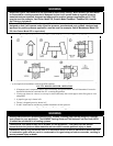
Repeat Step ‘d’ through step ‘p’ with the
following exceptions:
• During Step ‘d’ procedure, apply multi-
purpose spray adhesive to combustion
chamber rope groove as well as perimeter
groove.
• During Step ‘e’ procedure, locate 86”
length of red silicone coated berglass rope.
Starting at 9 o’clock position, push rope into
groove and continue around combustion
chamber until rope overlaps starting point.
Mark joint, cut-off excess and seal joint per
instructions.
• During Step ‘j’ procedure, apply sealant to
the (6) ueway sealing grooves on the center
section.
BE SURE TO APPLY THE SILICONE
COATED FIBERGLASS ROPE AND
SEALANT to the grooved joints between