


42
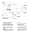
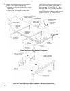
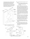
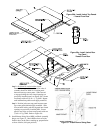
c. BSD with right hand hinge arrangement -
harness exits right side of jacket front panel en
route to control panel.
d. BSD with right hand hinge arrangement -
harness exits left side of jacket front panel en
route to control panel.
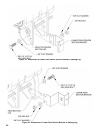
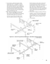
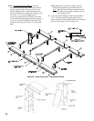
Locate two (2) cable clamps and secure harness to
vertical rails with two (2) #8 x ½ hex head sheet
metal screws as shown in Figure 24g, clamp must be
facing inward to prevent interference with jacket.
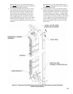
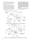
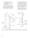
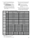
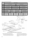
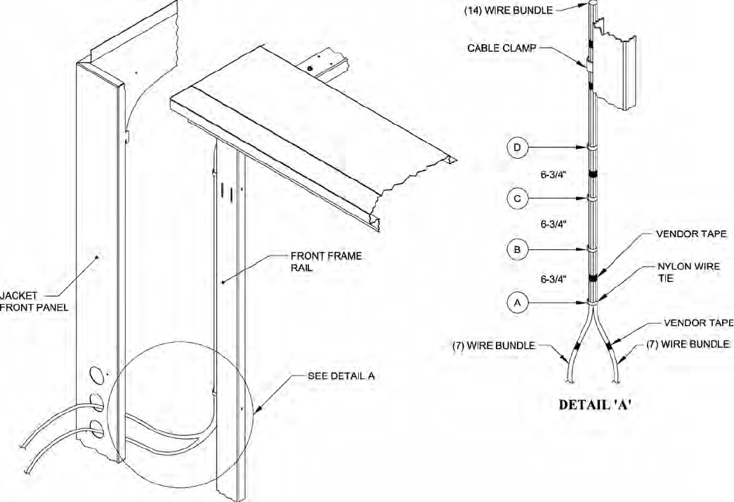
7. Adjust length of internal wiring harness to match
boiler size, see Table IX and Figure 25 for details.
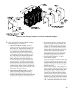
a. 4 thru 8 section boilers are shipped with the
internal harness length suitable for an 8 section
boiler. To modify harness for a 7 section, cut
nylon wire tie A; for a 6 section, cut A & B; for 5
section, cut A, B & C; and for a 4 section, cut A,
B, C & D. Refer to Table IX and Figure 25.
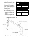
b. 9 thru 13 section boilers are shipped with the
proper harness length suitable for a 13 section
boiler. For boiler sizes 9 thru 12, modify harness
per Table IX, also refer to Figure 25.
c. 14 thru 18 section boilers are shipped with the
proper harness length suitable for an 18 section
boiler. For boiler sizes 14 thru 17, modify
harness per Table IX, also refer to Figure 25.
Figure 25: Internal Wiring Harness - Length Adjustment for Penetration Through Side of Jacket Front Panel