


22
adjacent sections as the boiler operates with a
positive pressure in the rebox and products of
combustion will escape between sections unless
they are properly sealed. The rope and sealant
should be applied before each section is placed
on the assembly.
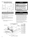
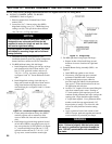
NOTICE
As assembled length increases, use 3/4” coupling
nuts and additional rods, provided in Kit, to extend
draw-up rod length.
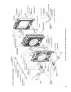
CONTINUE ASSEMBLING SECTIONS
IN THEIR RESPECTIVE ORDER until the
block assembly is complete. Be certain that all
sections are drawn up iron-to-iron at both nipple
ports.
D
O NOT REMOVE the draw-up tool, leave
it under tension until the retention rods are in
place.
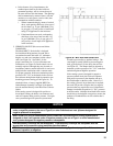
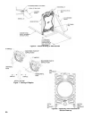
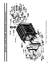
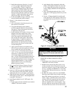
Locate the threaded 5/8” retention rods,
washers, tension springs and nuts supplied
in Boiler Assembly Carton marked ‘BAC’.
Assemble both top retention rod assemblies as
shown in Figure 5, Detail B, using the proper
arrangement per Table VI. The tension spring
should always be located at the rear of the boiler.
These rod assemblies can be lowered directly
into slotted lugs on each side of the upper nipple
port. Hand tighten the rear nuts only, do not
torque nut at this time.
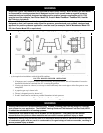
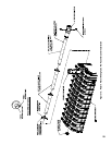
All casting legs have two (2) holes. Slide the
lower retention rods through the upper hole in
each leg. Start at the front or rear, which ever is
easiest, per the arrangement shown in Table VI.
With the rods in place, install a 5/8” at washer
and
5/8” hex nut on each rod protruding through
the front legs. On 8 through 18 section block
assemblies, additional rods and couplings nuts
are required to span the distance. On these larger
sizes, thread couplings on front rods to mid point
of coupling (halfway), pull next rod forward to
meet front coupling. Hold front coupling, not
front rod, while threading rear rod into coupling
nut until it contacts front rod at mid point.
Repeat this process until both lower rods
protrude through rear section legs. In the
following order, place a 5/8” at washer, 5/8”
tension spring and 5/8” hex nut on both rods.
Hand tighten rear nut only to remove all slack
from the lower rod assemblies. Use a torque
wrench adjusted for 20 ft/lb of torque to tighten
four (4) rear hex nuts. In lieu of a torque
wrench, use a combination wrench to tighten
nuts approximately ¾ turn beyond hand tight, to
set tension.
Excess length of draw-up rods must not extend
beyond front and rear section to ensure proper t
of
jacket, adjust accordingly.
Release tension on Manual Draw-up
Assemblies and remove.
Now proceed to Step C of this Section on Page
24, Hydrostatic Test.
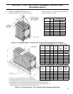
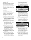
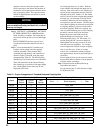
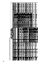
Model
Block Assembly Size Retention Rod / Coupling Nut Arrangement
Front
Section
Center
Section
Rear
Section
Front f Block Assembly g Rear
MPC4 1 2 1 24¼” Rod
MPC5 1 3 1 31” Rod
MPC6 1 4 1 37¾” Rod
MPC7 1 5 1 44½” Rod
MPC8 1 6 1 24¼” Rod / Nut / 27” Rod
MPC9 1 7 1 24¼” Rod / Nut / 34” Rod
MPC10 1 8 1 31” Rod / Nut / 34” Rod
MPC11 1 9 1 37¾”” Rod / Nut / 34” Rod
MPC12 1 10 1 44½” Rod / Nut / 34” Rod
MPC13 1 11 1 24¼” Rod / Nut / 27” Rod / Nut / 34” Rod
MPC14 1 12 1 31” Rod / Nut / 27” Rod / Nut / 34” Rod
MPC15 1 13 1 37¾” Rod / Nut / 27” Rod / Nut / 34” Rod
MPC16 1 14 1 44½” Rod / Nut / 27” Rod / Nut / 34” Rod
MPC17 1 15 1 44½” Rod / Nut / 34” Rod / Nut / 34” Rod
MPC18 1 16 1 31” Rod / Nut / 27” Rod / Nut / 27” Rod / Nut / 34” Rod
Table VI: Proper Arrangement of Threaded Rods and Coupling Nuts