


27
f. Install observation port sight glass. Locate 2”
x 2-1/2” lg. nipple, sight glass envelope and
2” conduit bushing. Thread 2” nipple into
observation port tapping directly above burner
adapter opening on front of BSD. Open sight
glass envelope and in this order place gasket,
sight glass and gasket into conduit cap. Thread
cap unto 2” nipple, hand tighten only until cap
and glass are snug. Do not over tighten.
g. Do not install BSD on hinges at this time. Door
must be installed after jacket assembly.
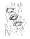
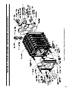
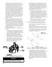
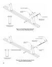
7. Mount C. I. ue collector to rear section -
see Figure 9.
a. Use a wire brush to clean the rope groove on
back surface of rear section.
b. Using the multi-purpose spray adhesive
provided, apply the adhesive to the perimeter
rope groove. Follow the directions on the can
for application and tack time.
c. Locate remaining 158” length of silicone coated
berglass rope from common parts carton.
Starting at 3 o’clock position, push rope into
groove and continue around perimeter until
rope overlaps the starting point. Rope should
be approximately 4” longer than required. Use
a permanent black marker to mark the rope
approximately 1/8” beyond point of overlap.
Cut off excess with scissors or utility knife and
wooden cutting block.
d. Apply a generous bead of red sealant to both
ends of cut rope, push ends together and smooth
excess sealant over joint with your nger.
e. Locate six (6) 3/8” at washers and six (6) 3/8
-16 x 1-1/4” lg. cap screws from hardware bag.
Thread one (1) washer and cap screw in each
of the bottom tappings approximately four (4)
turns. Lift ue collector and engage bottom slots
over cap screws to position unit on rear section.
Install remaining hardware in four (4) upper slots
and hand tighten hardware. Using a wrench,
tighten hardware evenly, use an alternating
pattern from top to bottom.
8. Do not install Flue Collector Clean-out Covers at
this time. Covers must be installed after Jacket
Rear Panels are in place.
9. Install 1/4” NPT brass plug into tapping located at
10 o’clock position on ue outlet collar. Wrench
tighten plug, but do not over tighten. See Figure 9.
10. Apply thread sealant and install 3” NPT pipe plug in
lower tapping on front section. Wrench tighten until
water tight. See Figure 9.
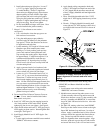
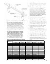
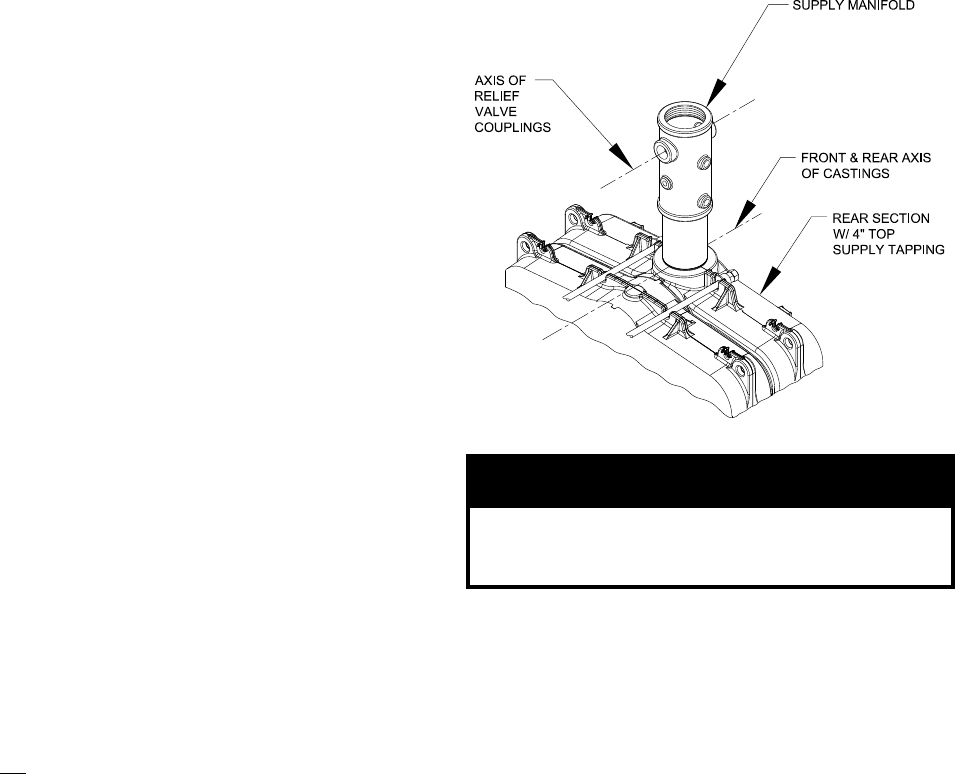
11. Install Supply Manifold and 4” NPT nipple - See
Figure 9.
a. Locate supply and return manifold carton marked
‘S/RM CI’ and remove contents.
b. Apply thread sealing compound to both ends
of the 4” NPT nipple and install one end of the
4” NPT nipple into the non-ow arrowed end
of the CI Supply Manifold and hand tighten the
assembly.
c. Then - Install the threaded end of the 4” NPT
nipple into 4” NPT tapping located on top of rear
section.
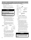
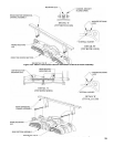
d. Wrench - CI Supply Manifold Assembly until
water tight and 1½” NPT tappings (relief valve)
are aligned with front and rear axis as shown in
Figure 12.
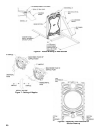
Figure 12: Orientation of Supply Manifold
NOTICE
Orientation of supply manifold is critical for
proper alignment of controls and relief valve
piping.
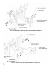
Assemble and Install Return Water Mixing Tube
(RWMT RC) and Return Manifold into Block
Assembly.
1. Locate return water mixing tube carton marked
‘RWMT RC’ and remove contents.
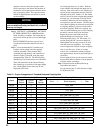
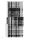
2. Modular return water mixing tubes start as a two
(2) tube assembly with end cap and increase with
block size to become a seven (7) tube assembly with
end cap. Assemble each RWMT RC in exact order
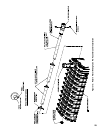
shown in Table VII based on boiler size. Also refer
to Figure 13.
3. Per Table VII, starting at the front, install RWMT
End Cap on tube shown in next column to the right.
Open ‘RH’ hardware bag and locate 3 oz. tube of
sealant. Apply a continuous bead of silver silicone
sealant to end of tube opposite the ared collar or
ring. The end cap and each tube has a series of
holes for alignment when secured together. Align
the holes, push end cap over tube end with sealant
and secure with four (4) #8 x 1/2 hex head screws.