


15
a. In the absence of local requirements, the
conned space shall be provided with two
permanent openings, one in or near the top of
the room and one near the bottom. The openings
shall communicate by means of ducts, with the
outdoors or to such spaces (crawl or attic) that
communicate with the outdoors.
i. Where communicating by means of vertical
ducts, each opening shall have a free area of
not less than 1 sq. in. per 4,000 Btuh (35 sq.
in. per gph.) (5.5 cm2 per kw) of total input
rating of all appliances in the enclosure.
ii. If horizontal ducts are used, each opening
shall have a free area of not less than 1 sq.
in. per 2,000 Btuh (70 sq. in. per gph.) (11
cm2 per kw) of total input of all appliances
in the enclosure.
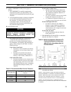
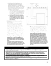
5. CHIMNEY OR VENT (Be sure to read below
WARNINGS.)
The Model MPC™ Series boiler is designed
for forced draft ring and may be used with a
conventional natural draft stack (15’ minimum
height) or a stub vent, sometimes called a diesel
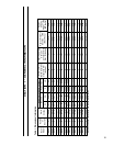
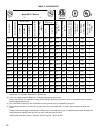
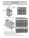
stack (see Figure 3a). See Table I for the
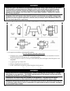
proper vent outlet size. For low silhouette vent
terminations, see Figure 3b. Draft controls are not
normally required, although they may be used on
installations where a natural draft stack is used or on
multiple boiler installations with a common stack.
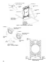
For proper operation, boiler must maintain positive
pressure of 0.1” W.C. at the breech in the cast iron
ue collector during burner high re operation (see
breeching pressure sensing port in Figure 1b). To
obtain the above, a factory supplied MPC Flue
Outlet Damper Assembly (see Page 56 for details)
must be attached directly to the Rear Flue Collector
Outlet.
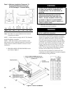
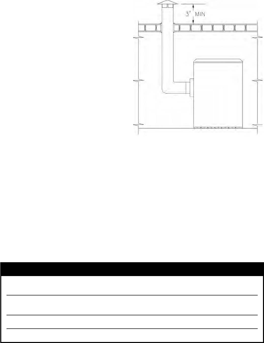
If the venting system is designed for positive or
forced draft venting, the boiler, vent connector and
stack will operate under positive pressure. Gas tight
vent systems designed for pressure systems must
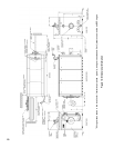
Figure 3a: MPC with Rear Outlet Vent
be used to prevent ue by-product leakage. The
vent height is usually limited to prevent negative
draft, typically three (3) feet above the roof line
(see Figure 3a). The damper shall be adjusted to
maintain a positive pressure of 0.1” W.C. at the ue
outlet during burner high re operation.
If the venting system is designed for negative
pressure (natural draft), the boiler still operates
with positive pressure in the chamber and up to
the xed damper on the ue collar. However, if
the venting system is larger than what is required,
the stack will provide a surplus draft (or negative
pressure) that may require the use of a barometric
damper to maintain the positive 0.1” W.C. pressure
at the ue outlet. Multiple forced draft boiler stacks
should always be designed as negative to ensure the
products of combustion do not exit a boiler that is
not ring.
NOTICE
When an MPC gas red boiler is connected to a venting system that is designed so that it will operate
under a negative pressure, the use of Type B, or other manufactured vent systems designed for
negative pressure is acceptable.
When an MPC oil red or combination gas/oil red boiler is connected to a venting system that is
designed so that it will operate under a negative pressure, the use of Type L or other manufactured
vent systems designed for negative pressure is acceptable.
Unlined masonry chimneys are not acceptable. Lined masonry chimneys are acceptable with the
appropriate vent connectors using materials described above.
MPC oil or combination gas/oil boilers should be vented using Type L vent, regardless if the vent
pressure is positive or negative.