


52
SSCI - Suburban Surgical Company, Inc.
Chapter 4 - Operation and Care
To stop the oxygen flow, press the oxygen on/off switch. The light
in the switch goes out and oxygen flow to the animal compartment
ceases. If it was On, the system light goes out.
To control the oxygen flow rate to the animal compartment, refer to
Controlling Oxygen Flow Rate on Page 56. To control oxygen
pressure, refer to Controlling Oxygen Pressure on Page 56.
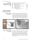
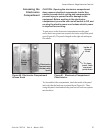
With the clear acrylic divider panel in place, it takes about 20-
minutes to bring the right animal compartment to an oxygen concen-
tration of 40%. Without the clear divider panel, it takes about 30-
minutes to bring the full compartment to 40%.
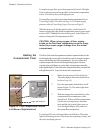
CAUTION: When using oxygen, all four access
knobs on the filter/fans compartment must be firmly
locked to prevent oxygen leakage from the animal
compartment.
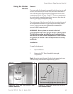
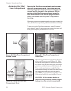
The floor of the animal compartment contains separate heaters for the
left and right sides to provide localized heat control when the compart-
ment is divided into two half-compartments. Two sets of floor heat
controls are provided for the left and right heating units. Each set
consists of an on/off button, a system light, a temperature controller,
and a digital display. To heat the entire compartment floor, turn both left
and right heaters On. To provide heat to the compartment:
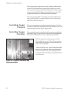
Heating the
Compartment Floor
1. Make sure the main on/off switch is On.
The amber light in the switch should be on
(refer to Page 48).
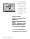
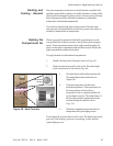
2. Press the appropriate heated floor on/off
button (Figure 55). The amber light in the
button comes on.
3. With the temperature control knob, set the
compartment floor temperature to the
desired level. If the actual floor temperature
is below the set temperature, the heater
starts and the red system light comes on.
View the digital display for a readout of
the current floor temperature.
To turn heat Off, press the heated floor on/off button. The amber
light in the button goes out. If the heater was operating, it stops, and
the red system light goes out.
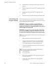
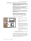
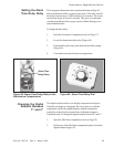
Figure 55. Floor Temperature Contols
(Left Shown, Right Identical)
On/Off
Button
System
Light
Temperature
Control Knob
Digital Display
Left Side Controls
Right Side Controls