


2. OPTION CABLE/CONNECTOR SETS
2 - 1
2. OPTION CABLE/CONNECTOR SETS
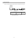
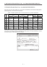
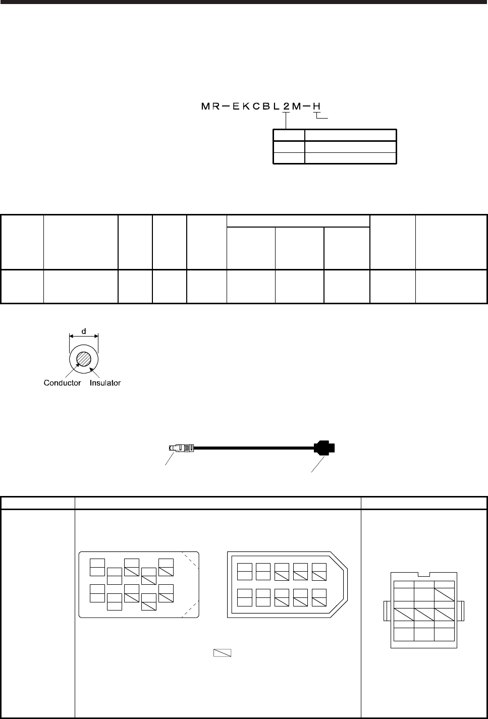
2.1 MR-EKCBL_M-H encoder cable
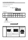
(1) Model explanations
2
5
2
5
Symbol
Cable length [m]
Long bending life
Model:
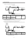
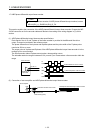
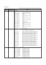
(2) Cable structure
The table shows this optional cable structure.
IP rating Bending life
Length
[m]
Core
size
[mm
2
]
Number
of cores
Characteristics of one core
(Note 2)
Cable OD
[mm]
Wire model
(manufacturer)
Structure
[Wires/mm]
Conductor
resistance
[Ω/km]
(Note 1)
Insulation
coating
OD d [mm]
IP20 Long bending life 2/5 0.2
12
(6 pairs)
40/0.08 105 or less 0.88 7.2
(Note 3)
A14B2339 6P
(Junkosha)
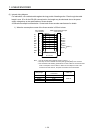
Note 1. d is as shown below.
2. Standard OD. Maximum OD is about 10% greater.
3. Purchase from Toa Electric Industry
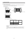
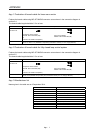
1)
2)
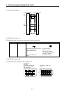
Cable model 1) SCALE-side connector of branch cable 2) Junction connector
MR-EKCBL_M-H Receptacle: 36210-0100PL
Shell kit: 36310-3200-008
(3M)
Connector set: 54599-1019
(Molex)
Housing: 1-172161-9
Connector pin: 170359-1
(TE Connectivity or equivalent)
Cable clamp: MTI-0002
(Toa Electric Industry)
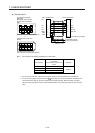
RQ
123
/RQ
456
P5
789
LG FG
V
iew seen from wiring side.
MRR
LG
P5
P5
MR
View seen from wiring side. (Note)
View seen from wiring side. (Note)
1 3
7 9
42 86 10
5
or
4
2
8
6
15
10
37
9
MRR
LG
MR
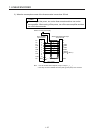
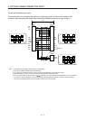
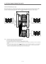
Note. Keep open the pins shown with . Especially, pin 10 is provided for
manufacturer adjustment. If it is connected with any other pin, the servo
amplifier cannot operate normally. Referring POINT of chapter 1, securely
connect the external conductor of the shielded cable to the ground plate
and fix it to the connector shell.