


1. LINEAR ENCODER
1 - 15
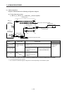
1.2.3 ST741A/ST742A/ST743A/ST744A
(1) Cable composition
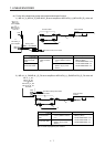
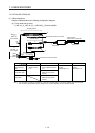
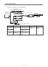
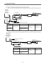
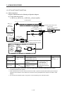
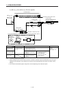
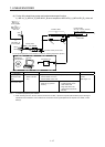
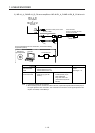
Prepare a cable based on the following configuration diagram.
(a) For the linear servo motor
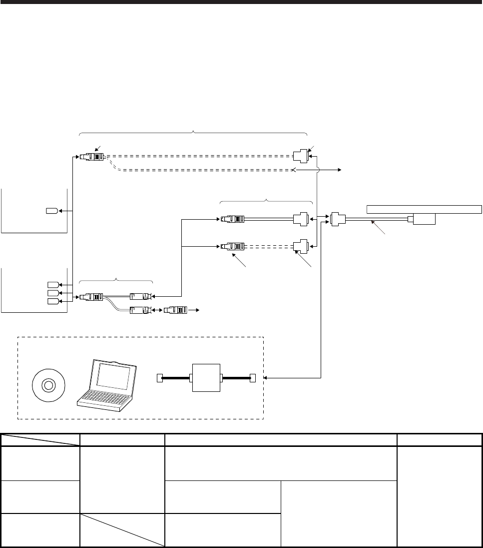
1) MR-J4-_A_, MR-J4-_B_, or MR-J4W_-_B servo amplifier
Personal
computer
Software for
signal adjustment
Conversion unit
For the signal adjustment and confirmation, connect the following equipments. (Note 3)
Head cable
Linear encoder
ST741A, ST742A, ST743A,
ST744A or ST748A
Encoder cable 1
Thermistor of linear servo motor
Branch cable
MR-J4W_-_B
servo amplifier
(Note 1)
or
MR-J4-_A_
or
MR-J4-_B_
servo amplifier
2) 3)
1)
CN2B
CN2A
CN2
CN2C
4) SCALECN2
3)5)
Thermistor of linear servo motor
THM (Note 4)
Encoder cable 2
Branch cable Encoder cable Head cable
When using an
optional encoder
cable
4) MR-J4THCBL03M
(Refer to section
2.4.)
1) Options manufactured by Mitutoyo (Note 2)
Part No.06ACF117A: 5 m
Part No.06ACF117B: 10 m
Accessories for linear
encoder
Cable length: 1 m
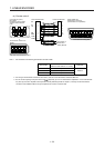
When fabricating
the encoder cable
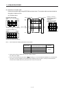
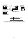
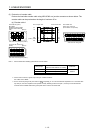
2) Connector set MR-J3CN2
(Refer to (2) (a) of this
section.)
3) Junction connector (Note 2)
D-SUB (female) 15 pin
Shell: HDAB-15S
Plug case: HDA-CTH
(manufactured by Hirose
Electric)
When not using a
branch cable
5) Connector set MR-J3CN2
(Refer to (2) (b) of this
section.)
Note 1. The connection to CN2C is for the MR-J4 3-axis servo amplifier. MR-J4 2-axis servo amplifier does not have CN2C.
2. It should be prepared by the customer.
3. When mounting ST741A, ST742A, ST743A, ST744A or ST748A, a personal computer (with RS-232C port) for the signal
adjustment and confirmation, and a software and conversion unit for signal adjustment are required. For details, contact
Mitutoyo.
4. For connectors for thermistor signals, change how to connect depending on the customer's system.