


1. LINEAR ENCODER
1 - 10
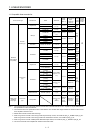
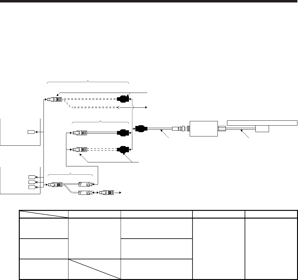
1.2.2 AT543A-SC/AT545A-SC
(1) Cable composition
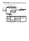
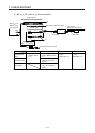
Prepare a cable based on the following configuration diagram.
(a) For the linear servo motor
1) MR-J4-_A_, MR-J4-_B_, or MR-J4W_-_B servo amplifier
Linear encoder
AT543A-SC or AT545A-SC
2)
1)
Encoder cable 1
Thermistor of linear servo motor
Branch cable
CN2B
CN2A
CN2
CN2C
MR-J4W_-_B
servo amplifier
(Note 1)
CN2 3) SCALE
THM
or
Output cable
Head cable
Thermistor of linear servo motor
4)
(Note 2)
MR-J4-_A_
or
MR-J4-_B_
servo amplifier
Encoder cable 2
Branch cable Encoder cable Output cable Head cable
When using an
optional encoder
cable
3) MR-J4THCBL03M
(Refer to section
2.4.)
1) MR-EKCBL_M-H
2 m/5 m (Refer to section
2.1.)
Accessories for linear
encoder
Cable length: 3 m
Accessories for linear
encoder
Cable length: 2 m
When fabricating
the encoder cable
2) Connector set MR-ECNM
(Refer to (2) (a) of this
section.)
When not using a
branch cable
4) Connector set MR-ECNM
(Refer to (2) (b) of this
section.)
Note 1. The connection to CN2C is for the MR-J4 3-axis servo amplifier. MR-J4 2-axis servo amplifier does not have CN2C.
2. For connectors for thermistor signals, change how to connect depending on the customer's system.