


1. LINEAR ENCODER
1 - 54
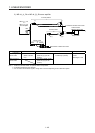
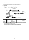
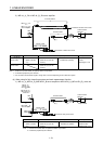
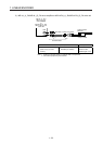
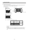
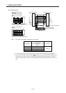
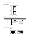
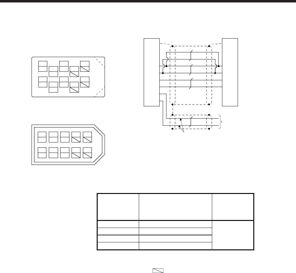
(b) Encoder cable 2
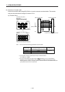
View seen from the wiring side. (Note 3)
1
P5
379
4
MRR
2
LG
8610
5
or
4
MRR
2
LG 8
6
1
P5
5
10
37
9
View seen from the wiring side. (Note 3)
MR
MR
Connector set: 54599-1019
(Molex)
Connector set (optional)
MR-J3CN2
Receptacle: 36210-0100PL
Shell kit: 36310-3200-008
(3M)
THM2
THM1
THM2
THM1
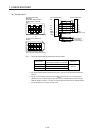
Connector: D-SUB 15 pin (female)
P5
LG
1
2
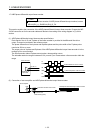
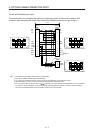
Servo amplifier side Linear encoder side
THM1
THM2 6
3
1 GND
VCC
SDSD
MR
MRR
3
4
5
7
8 /RQ / /DT
RQ / DT
Plate Plate
AWG 24 to 20
Thermistor of linear
servo motor (Note 2)
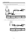
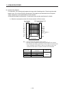
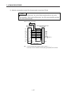
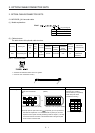
Note 1. We recommend the following specifications encoder cables.
Wiring length
Number of LG and P5
connections
(when the output cable is 0.5 m
or less)
Wire size
to 5 m 1-pair
to 10 m 2-pairs
AWG 22
to 20 m 4-pairs
to 30 m 5-pairs
2. For wiring to the thermistor of the linear servo motor, refer to "Linear Servo Motor Instruction Manual".
3. Do not connect anything to the pins shown as
. Especially, pin 10 is for manufacturer adjustment. If it is
connected with any other pin, the servo amplifier cannot operate normally. Referring POINT of chapter 1,
securely connect the external conductor of the shielded cable to the ground plate and fix it to the connector
shell.