


1. LINEAR ENCODER
1 - 29
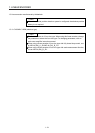
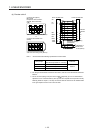
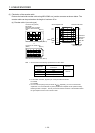
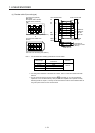
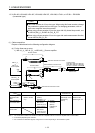
(2) Fabrication of the encoder cable
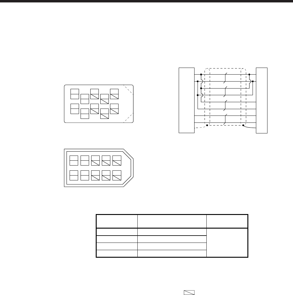
Produce the load-side encoder cable using MR-J3CN2 or a junction connector as shown below. The
encoder cable can be produced as the length of maximum 30 m.
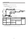
(a) Encoder cable 1 (two-wire type)
View seen from the wiring side. (Note 3)
1
P5
379
4
MRR
2
LG
8610
5
or
4
MRR
2
LG 8
6
1
P5
5
10
37
9
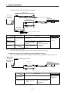
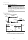
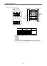
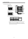
View seen from the wiring side. (Note 3)
MR
MR
Connector set: 54599-1019
(Molex)
Connector set (optional)
MR-J3CN2
Receptacle: 36210-0100PL
Shell kit: 36310-3200-008
(3M)
(Note 2)
(Note 2)
Connector: D-SUB
(female) 15 pin
P5
LG
1
2
Servo amplifier side Linear encoder side
0V
5V
SD Plate
0V/Sensor
5V/Sensor
MR
MRR
3
4
/RQ, /SD
RQ, SD
(Note 1)
4
2
FG
12
10
8
15
(Note 2)
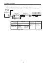
Note 1. We recommend the following specifications encoder cables.
Wiring length
Number of LG and P5
connections
Wire size
to 5 m 1-pair
to 10 m 2-pair
AWG 22
to 20 m 3-pair
to 30 m 4-pair
2. For the CN2L connector, signals of pin 3 and pin 4 will be as follows.
Pin 3: MR2
Pin 4: MRR2
3. Do not connect anything to the pins shown as
. Especially, pin 10 is for manufacturer
adjustment. If it is connected with any other pin, the servo amplifier cannot operate normally.
Referring POINT of chapter 1, securely connect the external conductor of the shielded cable to
the ground plate and fix it to the connector shell.