782
FX3S/FX3G/FX3GC/FX3U/FX3UC Series
Programming Manual - Basic & Applied Instruction Edition
35 SFC Program and Step Ladder
35.1 SFC Program
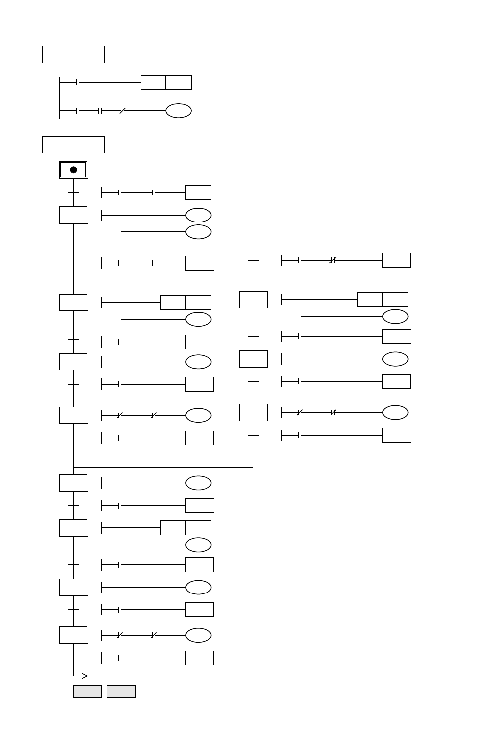
In an SFC program for selecting large or small products and judging products as either accepted or rejected, selective
branches and recombination are adopted as shown in the figure below.
M8002
Ladder block
S0SET
Initial pulse
21
0
1
SFC block
0
TRAN
X026
Y000
K20
Start
22
T1
K10
Y001SET
2
T1
23
3
24
30
4
RET END
TRAN
TRAN
TRAN
X001
Y007
X003 Y001
Origin
indication
Y007
Moving
down
T0
T0
Lower limit
switch: ON (small ball)
X002
Suction
Y002
Moving
up
X003
Y003
Moving
rightward
TRAN
X004
Right limit switch
(small bucket)
Y000
Moving
down
5
31
TRAN
X002
Lower limit switch
T2
Y001RST Release
K10
6
TRAN
T2
Y002
Moving
up
TRAN
X003
Upper limit switch
32
7
X004
33
8
Y004
Moving
leftward
TRAN
X001
X001
Left limit switch
0
9
25
10
26
11
27
12
Origin
TRAN
T0 X002
Lower limit
switch: OFF (large ball)
T1
K10
Y001SET Suction
T1
TRAN
TRAN
Y002
Moving
up
X003
Y003
Moving
rightward
TRAN
X005
Right limit switch
(large bucket)
X005
When a product is small (when X002
turns ON), the left flow is valid.
When a product is large, the right flow is
valid.
The ON status is transferred to the
recombination state relay S30 when
X004 turns ON in the case of a small
product, or when X005 turns ON in the
case of a large product.
When the special auxiliary relay
M8040 described later is driven, all
transfers to any state relay are
disabled.
In each of the state relays S24, S27
and S33, an interlock contact is
connected in series respectively to
the rightward movement output Y003
and leftward movement output Y004.
Left
limit
Upper
limit
Release
Upper limit switch
Upper limit switch
Y004
Y004
Y003


