


727
FX3S/FX3G/FX3GC/FX3U/FX3UC Series
Programming Manual - Basic & Applied Instruction Edition
33 Extension File Register Control – FNC290 to FNC299
33.3 FNC292 – INITR / Initialize R and ER
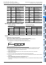
31
FNC277-FNC279
Data
Transfer 3
32
FNC280-FNC289
High-Speed
Processing 2
33
FNC290-FNC299
Extension File
Register Control
34
FNC300-FNC305
FX
3U
-CF-ADP
35
SFC•STL
Programming
36
Interrupt
Function
37
Special Device
38
Error Code
A
Version Up
Information
B
Execution Times
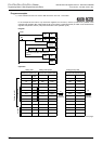
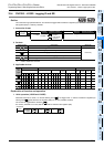
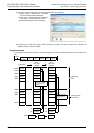
The table below shows the head device number in each sector:
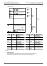
Operation (when a memory cassette is used)
Caution
1. Initialization of two or more sectors
When a memory cassette is attached, 18 ms is required to initialize one sector.
(When a memory cassette is not attached, only 1 ms or less is required to initialize one sector.)
When initializing two or more sectors, take either measure shown below.
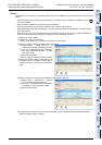
• Set a large value to the watchdog timer D8000 using the following program
Guideline of the watchdog timer set value
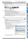
A value acquired by the following procedure can be regarded as the guideline of the watchdog timer set value.
If an acquired value is 200 ms or less, however, it is not necessary to change the watchdog timer set value.
1) Write a program to be executed from GX Works2 to the PLC.
[Online]→[Write to PLC...]
2) Set the current value of D8000 (unit: ms) to "1000" using the modify value function in GX Works2.
[Debug]→[Modify Value]
3) Set the PLC mode to RUN, and execute the program. (Execute this instruction also.)
4) Monitor the maximum scan time D8012 (unit: 0.1 ms) using the device/buffer memory batch monitor function in
GX Works2.
5) Set the watchdog timer to the maximum scan time (D8012) or more.
D8012 stores the maximum scan time in increments of 0.1 ms.
Rough guide to the watchdog timer set value D8000 (unit: ms) is the "value stored in D8012 divided by 10" added
by 50 to 100.
Sector
number
Head device
number
Initialized device range
Sector
number
Head device
number
Initialized device range
Sector 0 R0
R0 to R2047,
ER0 to ER2047
Sector 8 R16384
R16384 to R18431,
ER16384 to ER18431
Sector 1 R2048
R2048 to R4095,
ER2048 to ER4095
Sector 9 R18432
R18432 to R20479,
ER18432 to ER20479
Sector 2 R4096
R4096 to R6143,
ER4096 to ER6143
Sector 10 R20480
R20480 to R22527,
ER20480 to ER22527
Sector 3 R6144
R6144 to R8191,
ER6144 to ER8191
Sector 11 R22528
R22528 to R24575,
ER22528 to ER24575
Sector 4 R8192
R8192 to R10239,
ER8192 to ER10239
Sector 12 R24576
R24576 to R26623,
ER24576 to ER26623
Sector 5 R10240
R10240 to R12287,
ER10240 to ER12287
Sector 13 R26624
R26624 to R28671,
ER26624 to ER28671
Sector 6 R12288
R12288 to R14335,
ER12288 to ER14335
Sector 14 R28672
R28672 to R30719,
ER28672 to ER30719
Sector 7 R14336
R14336 to R16383,
ER14336 to ER16383
Sector 15 R30720
R30720 to R32767,
ER30720 to ER32767
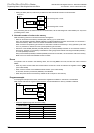
• Extension registers (R)
[inside the built-in RAM]
• Extension file registers (ER)
[inside the memory cassette]
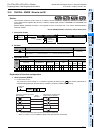
Device number
Current value
Device number
Current value
Before execution After execution Before execution After execution
H0010 HFFFF H1234 HFFFF
+1
H0020 HFFFF
+1
H5678 HFFFF
+2
H0011 HFFFF
+2
H90AB HFFFF
...
...
...
...
...
...
+(2048×n)-1
HABCD HFFFF
+(2048×n)-1
HCDEF HFFFF
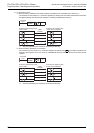
S
S
S
S
S S
S S
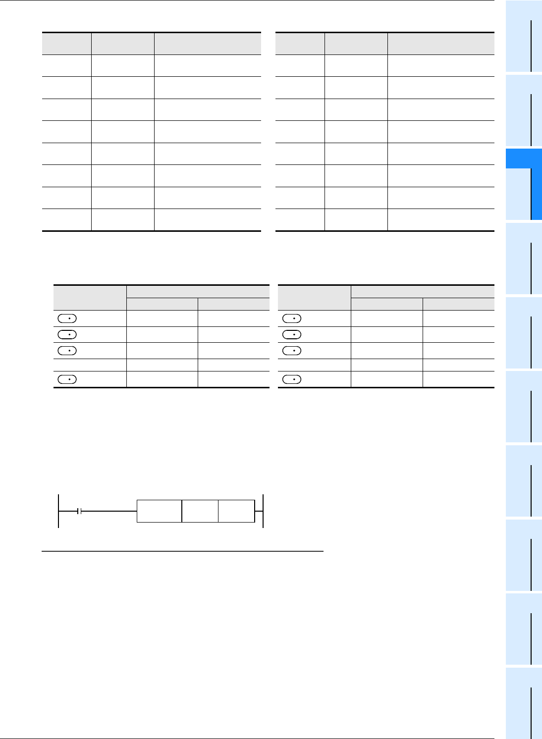
M8002
FNC 12
MOV
K
D8000
Initial pulse