437
FX3S/FX3G/FX3GC/FX3U/FX3UC Series
Programming Manual - Basic & Applied Instruction Edition
15 External FX I/O Device – FNC 70 to FNC 79
15.5 FNC 74 – SEGL / Seven Segment With Latch
11
FNC30-FNC39
Rotation and
Shift
12
FNC40-FNC49
Data Operation
13
FNC50-FNC59
High-Speed
Processing
14
FMC60-FNC69
Handy
Instruction
15
FNC70-FNC79
External FX I/O
Device
16
FNC80-FNC89
External FX
Device
17
FNC100-FNC109
Data
Transfer 2
18
FNC110-FNC139
Floating Point
19
FNC140-FNC149
Data
Operation 2
20
FNC150-FNC159
Positioning
Control
15.5.1 How to select a seven-segment display unit
When selecting a seven-segment display unit based on its electrical characteristics, refer to the manual below:
→ For the wiring, refer to the Hardware Edition of the PLC used.
1. Points to be checked for the seven-segment specifications
1) The input voltage and current characteristics of the data input and strobe signal satisfy the output specifications of
the PLC.
- The input signal voltage (Lo) is approximately 1.5 V or less
- The input voltage is from 5V DC to 30V DC
2) The seven-segment display unit has the BCD decoding and latch functions
15.5.2 How to select parameter "n" based on seven-segment display specifications
The value set to the parameter "n" varies depending on the signal logic of the seven-segment display. Select "n" as
described below.
The check column is provided at the bottom of the table. Check a corresponding type of logic (positive or negative),
and utilize it for parameter setting.
1. Role of the parameter "n"
The parameter "n" should be determined according to the data input logic (positive or negative) of the seven-segment
display unit, the logic (positive or negative) of the strobe signal and the number of sets of 4 digits to be controlled (1 or
2).
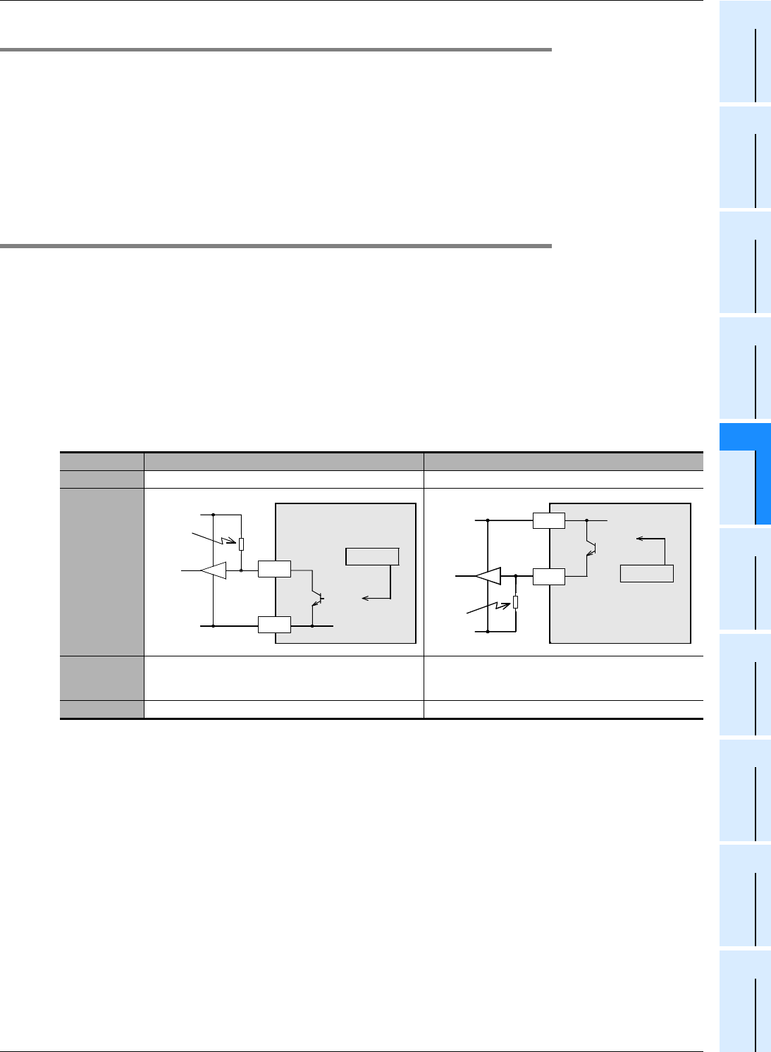
2. Checking the output logic of the PLC
Transistor outputs in PLCs are classified into the sink output type and source output type. The table below shows the
specifications for each type.
Logic Negative logic Positive logic
Output type Sink output (− common) Source output (+ common)
Output circuit
Description
Because transistor output (sink) is provided, the output
becomes low level (0 V) when the internal logic is "1 (ON
output)". This is called "negative logic".
Because transistor output (source) is provided, the output
becomes high level (V+) when the internal logic is "1 (ON
output)". This is called "positive logic".
Check
ON
PLC
LOW
Logic 1
Pull-up
resistor
COM1
Y000
ON
PLC
Logic 1
Pull-
down
resistor
V+
HIGH
+V0
Y000


