


417
FX3S/FX3G/FX3GC/FX3U/FX3UC Series
Programming Manual - Basic & Applied Instruction Edition
14 Handy Instruction – FNC 60 to FNC 69
14.9 FNC 68 – ROTC / Rotary Table Control
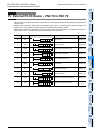
11
FNC30-FNC39
Rotation and
Shift
12
FNC40-FNC49
Data Operation
13
FNC50-FNC59
High-Speed
Processing
14
FMC60-FNC69
Handy
Instruction
15
FNC70-FNC79
External FX I/O
Device
16
FNC80-FNC89
External FX
Device
17
FNC100-FNC109
Data
Transfer 2
18
FNC110-FNC139
Floating Point
19
FNC140-FNC149
Data
Operation 2
20
FNC150-FNC159
Positioning
Control
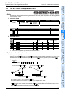
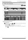
Operation conditions
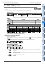
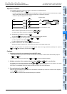
The conditions required to use this instruction are as shown in the example below.
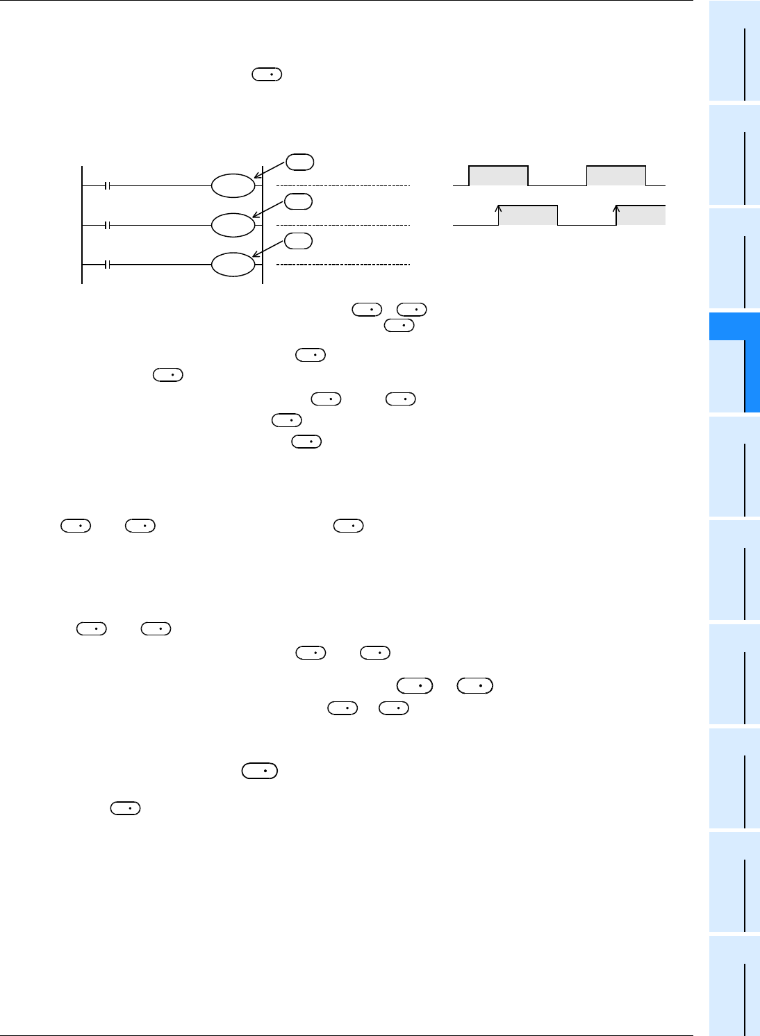
1) Rotation detection signal: X →
- Provide a 2-phase switch (X000 and X001) for detecting the rotation direction (forward or backward) of the table
and the switch X002 which turns ON when the product No. 0 reaches the port No. 0.
- Create the sequence program shown below.
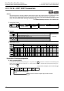
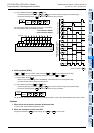
2) Specification of a register for counting:
The counter detects which number of product is located at the port No. 0.
3) Registers specifying the calling condition: +1 and +2
a) Set the port No. to be called in +1.
b) Set the product No. to be called in +2.
4) Number of divisions m1 and number of low-speed sections m2
Specify the number of divisions m1 of the table, and number of low-speed sections m2.
When the above conditions are specified, forward/backward rotation and high-speed/low-speed/stop are output to
+3 to +7 specified by the head device .
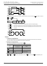
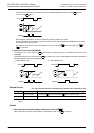
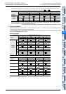
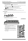
Cautions
1. Operations caused by the command input ON/OFF status
• When the command input is set to ON and this instruction is executed, the result will be automatically output to
+3 to +7.
• When the command input is set to OFF, +3 to +7 are set to OFF accordingly.
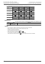
2. Multiple activation of the rotation detection signal ( to +2) in one division
For example, when the rotation detection signal ( to +2) is activated 10 times in one division, set a value
multiplied by "10" to each division, port No. to be called and product No. to be called.
As a result, an intermediate value of the division number can be set to a low-speed section.
3. Zero point detection signal
When the zero point detection signal (M2) turns ON while the command input is ON, the contents of the register for
counting are cleared to "0".
This clear operation should be executed before starting the operation.
D
1
D
X000
M0
X001
M1
X002
M2
D
D
D
+1
+2
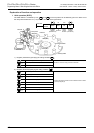
X000 to X002 are replaced with internal contacts of to +2.
An arbitrary head device number can be specified by X or .
Zero point detection switch
2-phase switch
B
phase
A
phase
Up-counting signal during forward rotation
D
D
D
D
1
S
D
1
S
D
1
S
D
1
S
D
1
S
D
1
S
D
1
D
D
1
D
D
1
D
D
1
D
D
1
D
D
1
D
D
1
D
D
1
D
D
1
D
D
1
D
D
1
D
D
1
D
D
1
S