


472
FX3S/FX3G/FX3GC/FX3U/FX3UC Series
Programming Manual - Basic & Applied Instruction Edition
16 External FX Device – FNC 80 to FNC 89
16.7 FNC 86 - VRSC / Volume Scale
Program example
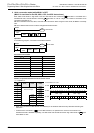
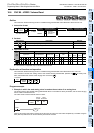
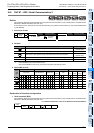
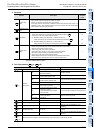
1. Example in which the scale value is used as a rotary switch
One of the auxiliary relays from M0 to M10 turns ON in accordance with the scale value ranging from 0 to 10 of the
specified variable analog potentiometer.
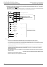
Cautions
•In FX3S PLC, the variable analog potentiometer board can be connected to the option connector.
In this case, the communication function is not available when the VRRD or VRSC instruction is used.
• In 14-point and 24-point type FX
3G PLCs, the variable analog potentiometer board can be connected to the option
connector 1, and occupies communication channel ch1.
In this case, the communication function using communication channel ch1 is not available when the VRRD or
VRSC instruction is used.
• In 40-point and 60-point type FX
3G PLCs, the variable analog potentiometer board can be connected only to the
option connector 2, and occupies communication channel ch2.
In this case, the communication function using communication channel ch2 is not available when the VRRD or
VRSC instruction is used.
• The communication function is not available for ch1 when the VRRD or VRSC instruction is used in the program in
FX
3U/FX3UC PLCs.
→ For details, refer to the Data Communication Edition manual.
•FX
3S/FX3G PLCs support the FX3G-8AV-BD.
•FX
3U/FX3UC-32MT-LT(-2) PLCs support the FX3U-8AV-BD.
K1
X000
FNC 86
VRSC
FNC 41
DECO
D1 M0 K4
X001
M0
M1
M10
D1
M0 turns ON when the scale value is "0".
M0 turns ON when the scale value is "1".
M0 turns ON when the scale value is "10".
The FNC 41 (DECO)
instruction occupies auxiliary
relays M0 to M15.