183
FX3S/FX3G/FX3GC/FX3U/FX3UC Series
Programming Manual - Basic & Applied Instruction Edition
7 Basic Instruction
7.1 LD, LDI
1
Introduction
2
Overview
3
Instruction
List
4
Devices
in Detail
5
Specified the
Device &
Constant
6
Before
Programming
7
Basic
Instruction
8
FNC00-FNC09
Program Flow
9
FNC10-FNC19
Move & Compare
10
FNC20-FNC29
Arith. & Logic
Operation
7.1 LD, LDI
Outline
LD and LDI instructions are contacts connected to bus lines.
When combined with ANB instruction described later, LD and LDI instructions can be used for the start of branches.
1. Instruction format
→ For the number of instruction steps, refer to Section 7.16.
2. Applicable devices
S1: Special auxiliary relays (M) and 32-bit counters (C) cannot be indexed with index registers (V and Z).
S2: State relays (S) cannot be indexed with index registers (V and Z).
S3: "D.b" is available only in FX
3U and FX3UC PLCs. However, index modifiers (V and Z) are not available.
S4: This function is supported only in FX
3U/FX3UC PLCs.
Explanation of function and operation
1. LD instruction (initial logical operation, NO contact type)
Instruc-
tion
Bit Devices Word Devices Others
System User Digit Specification System User
Special
Unit
Index
Con-
stant
Real
Number
Charac-
ter String
Pointer
XYMTCSD.b KnX KnY KnM KnS T C D R U\G V Z Modify K H E ""P
LD
S
1
S
1
S
2
S3 S4
LDI
S
1
S
1
S
2
S3 S4
LD
Load
Basic Instruction
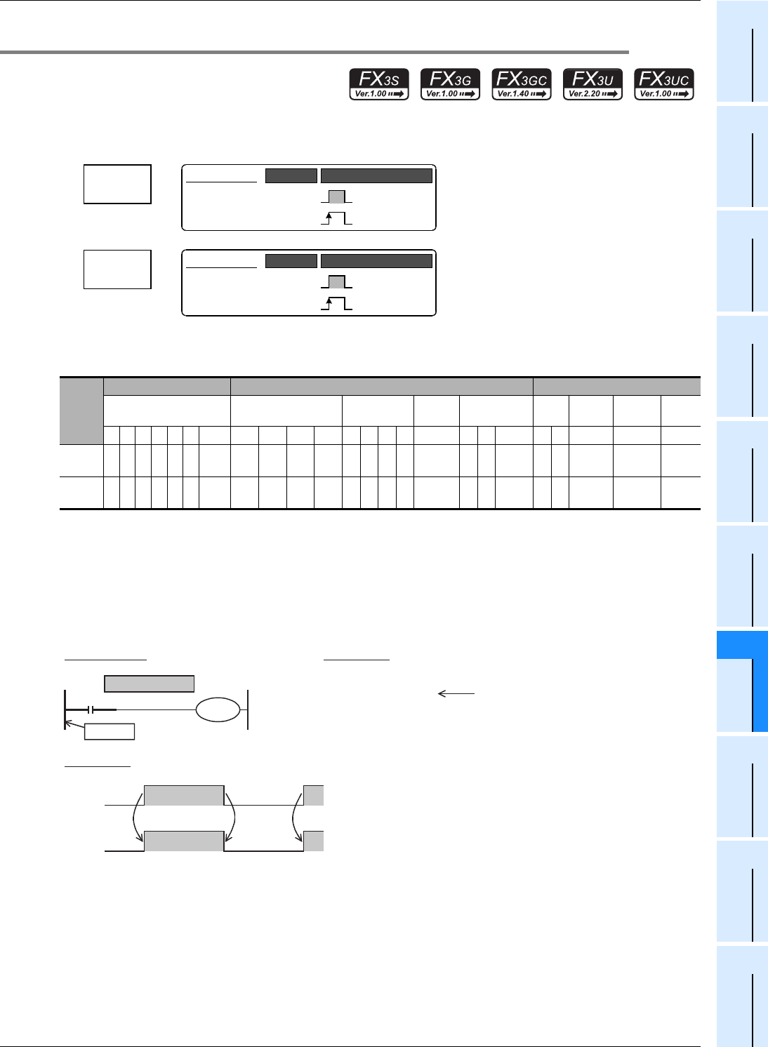
LD
−
Continuous
Operation
Pulse (Single)
Operation
Mnemonic Operation Condition
LDI
Load
Inverse
Basic Instruction
LDI
−
Continuous
Operation
Pulse (Single)
Operation
Mnemonic Operation Condition
X000
Y000
LD instruction
Circuit program List program
LD
OUT
0000
0001
X000
Y000
Connection to bus line
ONON
X000
ONON
Y000
Timing chart
Bus line


