691
FX3S/FX3G/FX3GC/FX3U/FX3UC Series
Programming Manual - Basic & Applied Instruction Edition
30 External Device Communication – FNC270 to FNC276
30.4 FNC273 – IVWR / Inverter Parameter Write
21
FNC160-FNC169
Real Time Clock
Control
22
FNC170-FNC179
External Device
23
FNC180
Alternate
Instructions
24
FNC181-FNC189
Others
25
FNC190-FNC199
Block Data
Operation
26
FNC200-FNC209
Character String
Control
27
FNC210-FNC219
Data
Operation 3
28
FNC220-FNC249
Data
Comparison
29
FNC250-FNC269
Data Table
Operation
30
FNC270-FNC276
Ex-Device
30.4 FNC273 – IVWR / Inverter Parameter Write
Outline
This instruction writes an inverter parameter of an inverter using the computer link operation function of the inverter.
This instruction corresponds to the EXTR (K13) instruction in the FX
2N/FX2NC Series.
→ For detailed explanation of the instruction, refer to the Data Communication Edition manual.
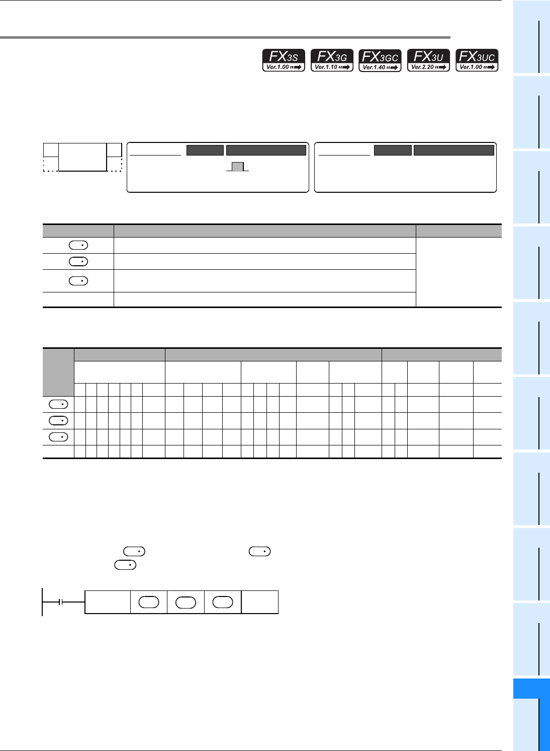
1. Instruction format
2. Set data
*1. Ch2 is not available in FX3G PLC (14-point and 24-point type) and FX3S PLC.
3. Applicable devices
S1: This function is supported only in FX3G/FX3GC/FX3U/FX3UC PLCs.
S2: This function is supported only in FX3U/FX3UC PLCs.
Explanation of function and operation
→ For detailed explanation of the instruction, refer to the Data Communication Edition manual.
1. 16-bit operation (IVWR)
A value specified in is written to a parameter in an inverter connected to a communication port n whose
station number is .
Operand Type Description Data Type
Inverter station number (K0 to K31)
16-bit binary
Inverter parameter number
Set value to be written to the inverter parameter or device number storing the data to be
set
n
Channel to be used (K1: ch 1, K2: ch 2)
*1
Oper-
and
Type
Bit Devices Word Devices Others
System User Digit Specification System User
Special
Unit
Index
Con-
stant
Real
Number
Charac-
ter String
Pointer
XYMTCSD
.b KnX KnY KnM KnS T C D R
U\G
V Z Modify K H E "
"P
S1 S2
S1 S2
S1 S2
n
FNC 273
IVWR
Mnemonic Operation Condition
16-bit Instruction
9 steps
IVWR
Mnemonic Operation Condition
Continuous
Operation
32-bit Instruction
⎯
⎯⎯
S
1
S
2
S
3
S
1
S
2
S
3
S
3
S
2
S
1
FNC273
IVWR
S
1
S
2
S3
n
Command
input


