


429
FX3S/FX3G/FX3GC/FX3U/FX3UC Series
Programming Manual - Basic & Applied Instruction Edition
15 External FX I/O Device – FNC 70 to FNC 79
15.3 FNC 72 – DSW / Digital Switch (Thumbwheel Input)
11
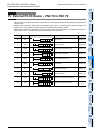
FNC30-FNC39
Rotation and
Shift
12
FNC40-FNC49
Data Operation
13
FNC50-FNC59
High-Speed
Processing
14
FMC60-FNC69
Handy
Instruction
15
FNC70-FNC79
External FX I/O
Device
16
FNC80-FNC89
External FX
Device
17
FNC100-FNC109
Data
Transfer 2
18
FNC110-FNC139
Floating Point
19
FNC140-FNC149
Data
Operation 2
20
FNC150-FNC159
Positioning
Control
15.3 FNC 72 – DSW / Digital Switch (Thumbwheel Input)
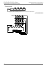
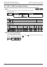
Outline
This instruction reads the set value of digital switches.
This instruction can read a set of 4 digits (n = K1) or two sets of 4 digits (n = K2).
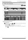
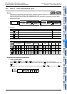
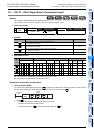
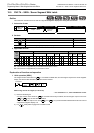
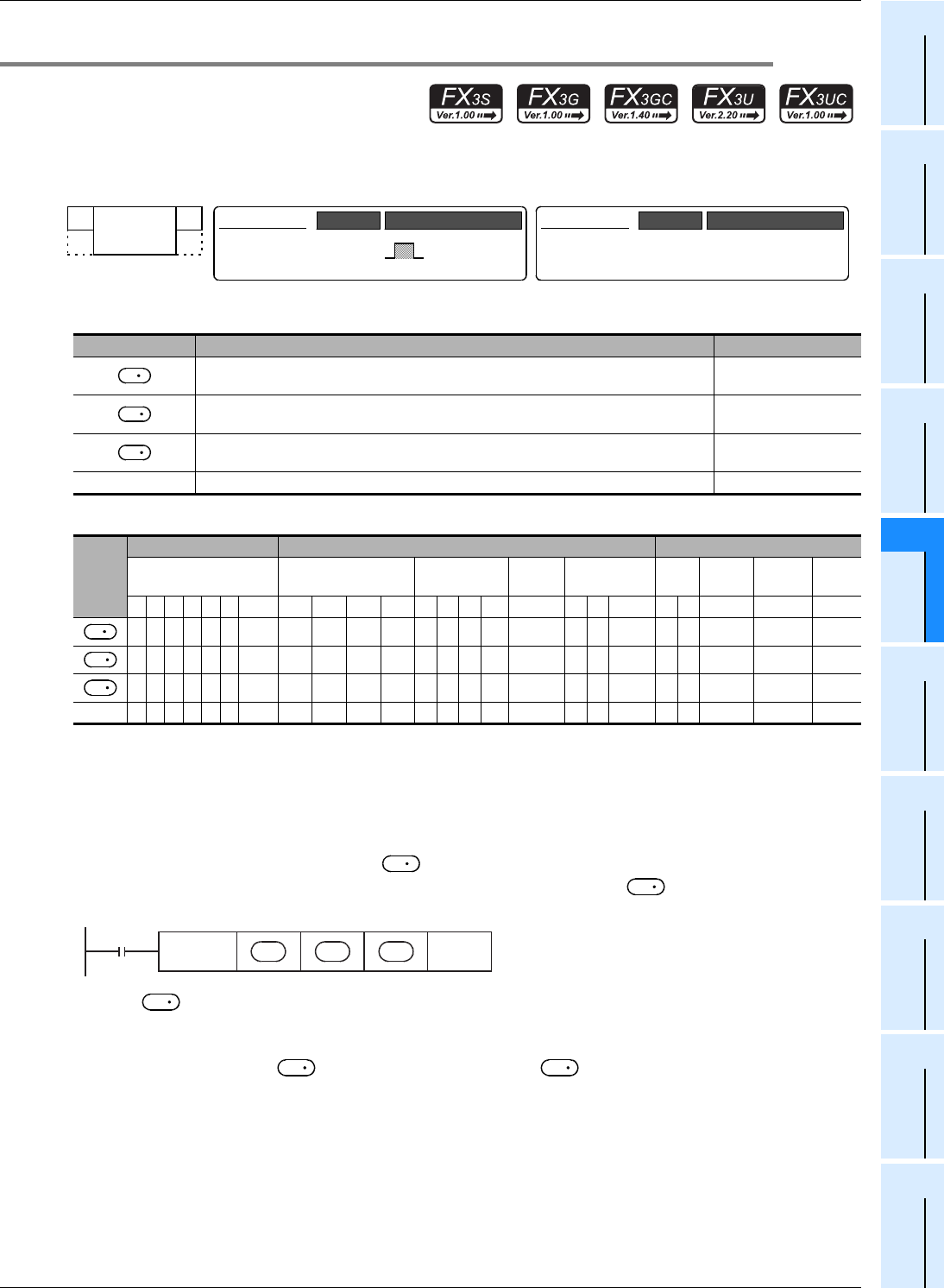
1. Instruction format
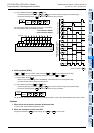
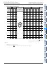
2. Set data
3. Applicable devices
S1: This function is supported only in FX3G/FX3GC/FX3U/FX3UC PLCs.
S2: This function is supported only in FX
3U/FX3UC PLCs.
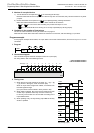
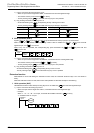
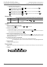
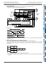
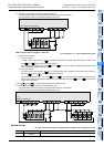
Explanation of function and operation
1. 16-bit operation (DSW)
The value of each digital switch connected to is input by the time division method (in which the value is input in
turn from the 1st digit by the output signal at the interval of 100 ms), and stored to .
1) Data
- A numeric value from 0 to 9999 (up to 4 digits) can be read.
- A numeric value is stored in binary format.
- The first set is stored to , and the second set is stored to +1.
Operand Type Description Data Type
Head device (X) number connected to a digital switch
(Four devices are occupied.)
Bit
Head device (Y) number to which the strobe signal is output
(Four devices are occupied.)
Bit
Device number storing the numeric value of a digital switch
("n" devices are occupied.)
16-bit binary
n Total number of 4-digit switch sets (4 digits/set) (n = 1 or 2) 16-bit binary
Oper-
and
Type
Bit Devices Word Devices Others
System User Digit Specification System User
Special
Unit
Index
Con-
stant
Real
Number
Charac-
ter String
Pointer
XYMTCSD
.b KnX KnY KnM KnS T C D R
U\G
V Z Modify K H E "
"P
S1 S2
n
FNC 72
DSW
DSW
16-bit Instruction
9 steps
Mnemonic Operation Condition
Continuous
Operation
−
32-bit Instruction
Mnemonic Operation Condition
S
D
1
D
2
S
D
1
D
2
S
D
2
FNC 72
DSW
n
Strobe
signal
D
1
S D
2
Command
input
D
1
D
2
D
2