


163
FX3S/FX3G/FX3GC/FX3U/FX3UC Series
Programming Manual - Basic & Applied Instruction Edition
5 How to Specify Devices and Constants to Instructions
5.7 Indexing
1
Introduction
2
Overview
3
Instruction
List
4
Devices
in Detail
5
Specified the
Device &
Constant
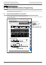
6
Before
Programming
7
Basic
Instruction
8
FNC00-FNC09
Program Flow
9
FNC10-FNC19
Move & Compare
10
FNC20-FNC29
Arith. & Logic
Operation
Cautions
1) When even if a numeric value written to index registers does not exceed the 16-bit numeric value range (0 to
32767), make sure to overwrite both V and Z using a 32-bit instruction. If only Z is overwritten and another
numeric value remains in V, the numeric value will be extremely large. Thus an operation error occurs.
2) It is not permitted to use 16-bit counters as 32-bit counters by executing indexing.
When 32-bit counters are required, add Z0 to Z7 to counters C200 and later.
3) It is not permitted to index V and Z themselves.
4) Direct specification of buffer memory in special function units/blocks
In the direct specification of buffer memory "U\G", the buffer memory number can be indexed with index
registers.
The unit number cannot be indexed with index registers.
("U0\G0Z0" is valid, but "U0Z0\G0" is invalid.)
5) Indexing in bit digit specification
It is not permitted to index "n" in "Kn" used for digit specification.
("K4M0Z0" is valid, but "K0Z0M0" is invalid.)
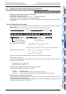
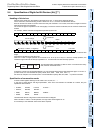
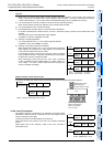
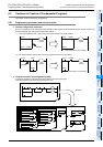
6) Indexing of I/O relays (octal device numbers)
When octal device numbers of X, Y, KnX, and KnY are indexed with
index register, the contents of an index register are converted into
octal, and then added to the device number.
In the example shown in the figure on the right, Y007 to Y000 are
output by MOV instruction, and inputs are switched by indexing X007
to X000, X017 to X010, and X027 to X020.
When rewriting the index value as "K0", "K8", "K16", the device
number converted into octal is added "X000 + 0 = X000", "X000 + 8 =
X10", "X000 + 16 = X20", and the input terminal working as the
source is changed accordingly.
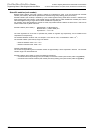
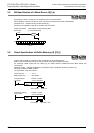
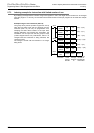
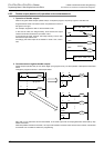
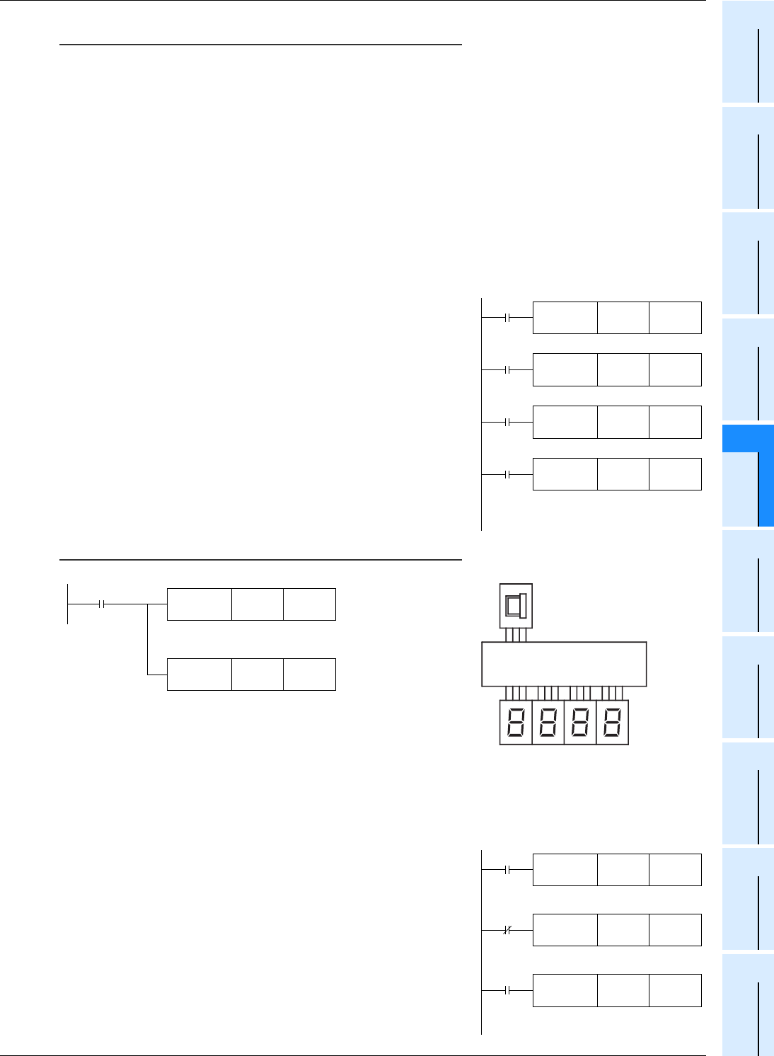
Display example of timer present value
A sequence to display the present value of the timers T0 to T9 can be programmed index registers.
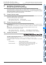
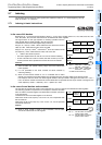
In the case of constants
The indexing operation is explained in an example in which the transfer
destination in MOV instruction is indexed with the index register V6 (as
shown in the figure on the right).
Transfer K0 or K20 to the index register V6 in advance.
When X005 is set to ON, "K(6+0) = K6" if V6 is "0", and K6 is transferred
to D10.
When X005 is set to ON, "K(6+20) = K26" if V6 is "20", and K26 is
transferred to D10.
X030
FNC 12
MOVP
K 0 V 3
K 0
→
V 3
FNC 12
MOVP
K 8 V 3
K 8
→
V 3
X033
FNC 12
MOV
K2X0V3 K2Y0
V3=0 : X7 to X0
→
Y7 to Y0
V3=8 : X17 to X10
→
Y7 to Y0
V3=16 : X27 to X20
→
Y7 to Y0
X031
FNC 12
MOVP
K 16 V 3
K16
→
V 3
X032
M8000
RUN monitor
FNC 19
BIN
K1X000 Z0
(X003 to X000)BCD
→
(Z0)BIN
FNC 18
BCD
T 0Z0 K4Y000
(T0Z0)BIN
→
(Y017 to Y000)BCD
"T0Z0 = T0 to T9" according to "Z0 = 0 to 9"
5
PLC
Digital switch input
for setting timer
number X003 to X000
Seven-segment display unit
output for displaying
timer current value
Y017 to Y000
X004
K0 V6
K0
→
V6
X004
K20 V6
K20
→
V6
X005
K6V6 D10
V6=0 : K6 (K6+0)
→
D10
V6=20 : K26(K6+20)
→
D10
FNC 12
MOVP
FNC 12
MOVP
FNC 12
MOVP