


590
FX3S/FX3G/FX3GC/FX3U/FX3UC Series
Programming Manual - Basic & Applied Instruction Edition
24 Others – FNC181 to FNC189
24.3 FNC186 – DUTY / Timing Pulse Generation
24.3 FNC186 – DUTY / Timing Pulse Generation
Outline
This instruction generates the timing signal whose one cycle corresponds to the specified number of operation cycles.
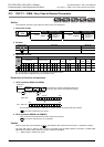
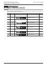
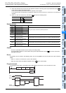
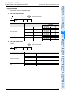
1. Instruction format
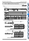
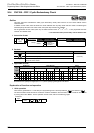
2. Set data
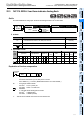
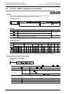
3. Applicable devices
S: Specify either one among M8330 to M8334.
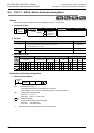
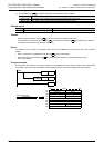
Explanation of function and operation
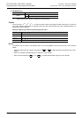
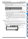
1. 16-bit operation (DUTY)
1) The timing clock output destination is set to ON and OFF with the ON duration for "n1" scans and OFF
duration for "n2" scans.
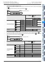
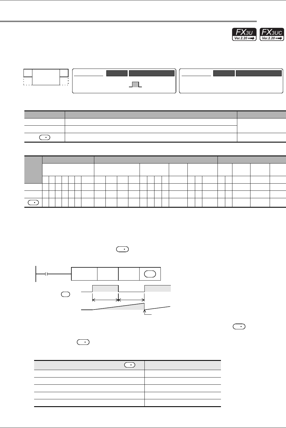
2) Specify either one among M8330 to M8334 as the timing clock output destination device .
3) The counted number of scans is stored among D8330 to D8334 in accordance with the timing clock output
destination device .
The counted number of scans stored among D8330 to D8334 is reset when the counted value reaches "n1+n2" or
when the command input (instruction) is set to ON.
Operand Type Description Data Type
n1 Number of scans (operation cycles) to remain ON [n1 > 0]
16-bit binary
n2 Number of scans (operation cycles) to remain OFF [n2 > 0]
Timing clock output destination Bit
Oper-
and
Type
Bit Devices Word Devices Others
System User Digit Specification System User
Special
Unit
Index
Con-
stant
Real
Number
Charac-
ter String
Pointer
XYMTCSD
.b KnX KnY KnM KnS T C D R
U\G
V Z Modify K H E "
"P
n1
n2
S
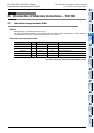
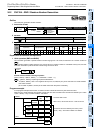
Timing clock output destination device
Scan counting device
M8330 D8330
M8331 D8331
M8332 D8332
M8333 D8333
M8334 D8334
FNC 186
DUTY
−
Mnemonic Operation Condition
16-bit Instruction
7 steps DUTY
Mnemonic Operation Condition
Continuous
Operation
32-bit Instruction
D
D
D
Command
input
FNC186
DUTY
n1 n2
Timing clock output
destination
Timing clock output
destination
D
OFF
"n1" scans
ON
"n1+n2" scans
0
"n2" scans
D
D
D
D