


392
FX3S/FX3G/FX3GC/FX3U/FX3UC Series
Programming Manual - Basic & Applied Instruction Edition
14 Handy Instruction – FNC 60 to FNC 69
14.1 FNC 60 – IST / Initial State
14.1.2 Example of IST instruction introduction (example of workpiece transfer mechanism)
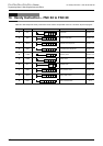
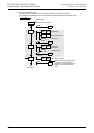
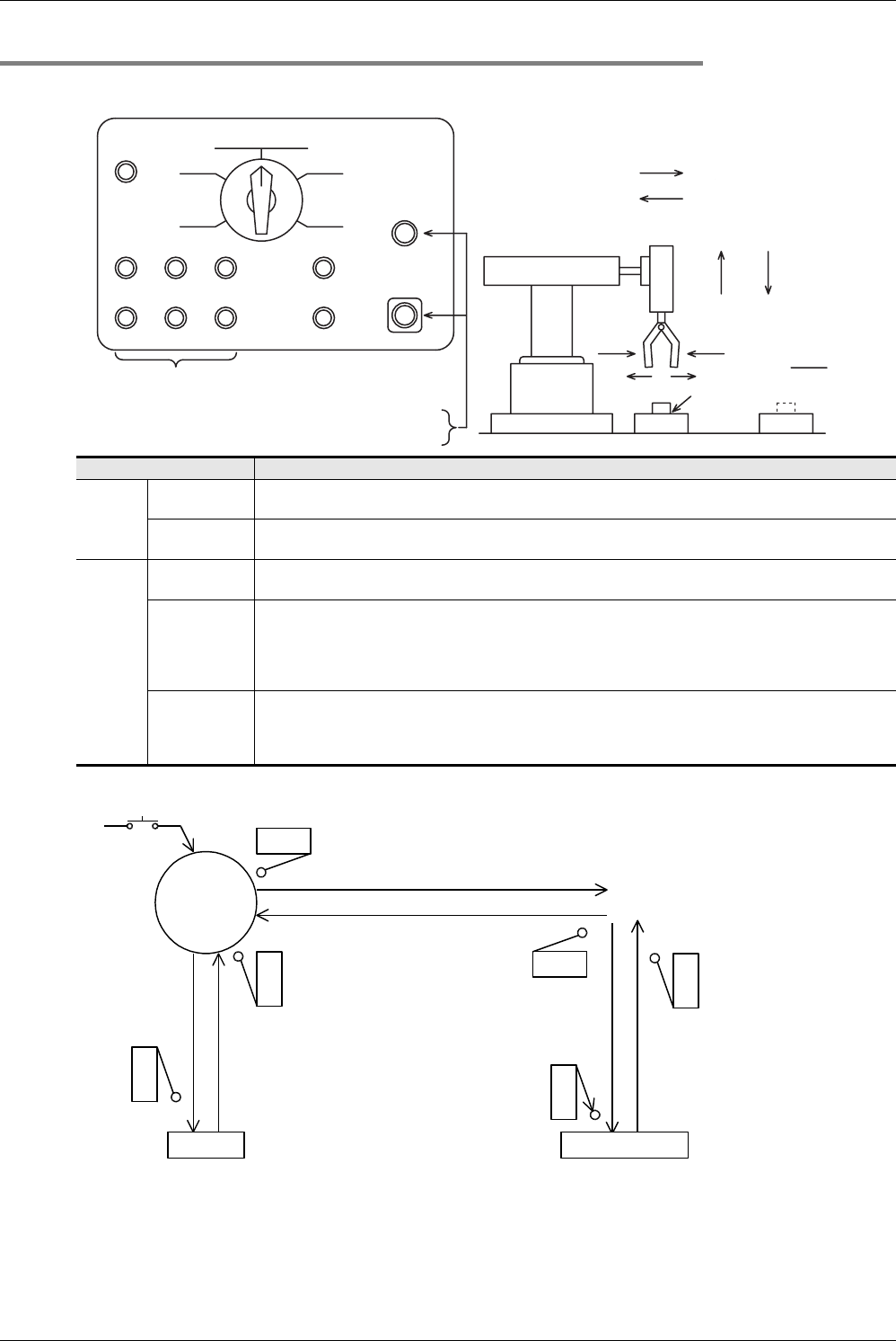
1. Operation mode
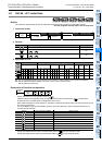
2. Transfer mechanism
The upper left position is regarded as the zero point. The machine transfers a workpiece from the left to the right in the
order "moving down → clamping → moving up → rightward travel → moving down → unclamping → moving up →
leftward travel".
Double-solenoid type solenoid valves (with two inputs for driving and non-driving) are adopted for moving down,
moving up, leftward travel and rightward travel. Single type solenoid valves (which operate only while the power is ON)
are adopted for clamping.
Operation mode Contents of operation
Manual
mode
Individual
operation mode
Each load is turned ON and OFF by an individual pushbutton switch.
Zero return
operation mode
When the pushbutton switch for zero return is pressed, the machine automatically returns to the zero point.
Auto-
matic
mode
Stepping
operation mode
Every time the start button is pressed, the machine performs one process.
Cycle operation
mode
When the start button is pressed while the machine is located at the zero point, the machine performs one
cycle of automatic operation and stops at the zero point.
If the stop button is pressed in the middle of one cycle, the machine stops immediately. When the start
button is pressed after that, the machine performs the continuous operation from the last position, and
automatically stops at the zero point.
Continuous
operation mode
When the start button is pressed while the machine is located at the zero point, the machine starts
continuous operation.
When the stop button is pressed, the machine finishes the current cycle until the zero point, and then stops
at the zero point.
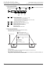
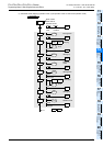
Unclamping Y001
Pushbutton switches for the external circuit to
turn ON and OFF the load power supply
X025
X021
X020
X022
X023
X024
Start X 026
Stop X027
X005 X006 X007
X010 X011 X012
PB PB PB
PB PB PB
PB
PB
PB
PB
PB
Zero return
Zero return
operation mode
Stepping
operation
Individual
operation mode
Moving up
Leftward
travel
Unclamping
Moving down
Rightward
travel
Clamping
Continuous
operation mode
Cycle
operation mode
Power supply
Emergency stop
Pushbutton switches for individual operations
of the robot hand shown in the figure on the right
Left limit X004
Y004
Y003
Rightward Right limit X003
Leftward
Y002 Y000
Upper
limit X002
Moving down
Moving
up
Clamping Y001
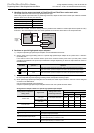
Workpiece
Point A Point B
Mechanism for transferring a workpiece from the
point A to the point B using the robot hand
Lower
limit X001
Zero point
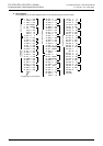
Left limit X004
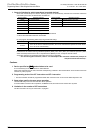
Start
X026
Upper limit X002
Clamping
Lower
limit
X001
(1) Moving
down
Y000
(3) Moving up
Y002
(2) Clamping
Y001 ON
Upper
limit
X002
Unclamping
Lower
limit
X001
(1) Moving down
Y000
(7) Moving up
Y002
(6) Unclamping
Y001 OFF
Right limit
X003
(4) Rightward Y003
(8) Leftward Y004
What is the zero point condition?
Upper limit X002 is ON, left limit
X004 is ON and unclamping Y001
is OFF.