151
FX3S/FX3G/FX3GC/FX3U/FX3UC Series
Programming Manual - Basic & Applied Instruction Edition
4 Devices in Detail
4.12 Pointer [P and I]
1
Introduction
2
Overview
3
Instruction
List
4
Devices
in Detail
5
Specified the
Device &
Constant
6
Before
Programming
7
Basic
Instruction
8
FNC00-FNC09
Program Flow
9
FNC10-FNC19
Move & Compare
10
FNC20-FNC29
Arith. & Logic
Operation
Operations
2. Pointers for timer interrupt: 3 points
→ For details on timer interrupt function, refer to Section 36.5.
The PLC executes an interrupt routine program at every specified interrupt cycle time (10 to 99 ms).
Use these pointers for control requiring cyclic processing regardless of the operation cycle of the PLC.
*1. Cleared when the PLC mode switches from RUN to STOP.
Caution
It is recommended to set the timer interrupt time to 10 ms or more. When the timer interrupt time is set to 9 ms or less,
the timer interrupt processing may not be executed at an accurate cycle in the following cases:
• When the processing time of the interrupt program is long
• When an instruction requiring long processing time is used in the main program
Input No. Interrupt cycle (ms) Interrupt disabling flag
I6
An integer ranging from 10 to 99 is put in "" portion of the pointer name.
Ex: I610 = Timer interrupt at every 10 ms
M8056
*1
I7
M8057
*1
I8
M8058
*1
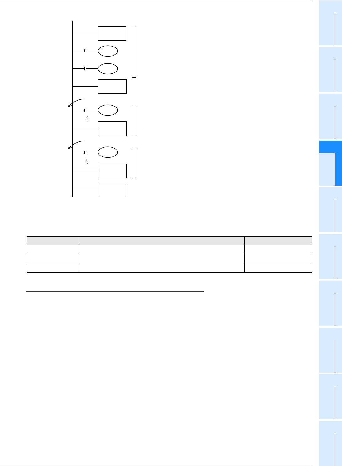
I001
FNC 04
EI
FNC 06
FEND
FNC 03
IRET
Pointer for
interrupt
Rising edge of X000 is detected
Interrupt enabled
range
Interrupt routine [1]
I101
FNC 03
IRET
Pointer for
interrupt
Rising edge of X001 is detected
Interrupt routine [2]
END
Interrupt is usually disabled in the PLC.
If interrupt is enabled by EI instruction, when
X000 or X001 turns ON while a program is
scanned, the PLC executes the interrupt
routine [1] or [2], and then returns to the main
program by IRET instruction.
•
Make sure to program a pointer for interrupt
(I***) as a label after FEND instruction.
•


